
Eureka
For R&D, Eureka makes reading and utilizing patents & technical documents easy.
Eureka AIR
Designed for self-driven R&D workflows. Generate viable solutions, solve complex R&D challenges, empower your innovation with AI.

Eureka Materials
Designed for material experts only. Revolutionize your material R&D, from search, analyze, to developing new materials.

TechResearch
Generate reliable direction feasibility study reports for your R&D in just a few steps.

TechSeek
Discover and master advanced knowledge NOW. Basics, ideas, possibilities, all at once.

TechMind
As an expert in R&D Theories, TechMind can generates customized viable solutions instantly.

TechRisk
Analyze your overall solution with one click, know your potential R&D risks in advance.

TechMonitor
Get weekly tech updates, stay abreast of the latest tech innovations and key insights.
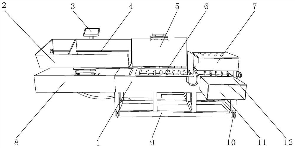
Waste cloth processing equipment for leather cloth production
A technology for processing equipment and cloth, which is applied in grain processing, solid waste removal, presses, etc., can solve the problems that the cloth cannot be introduced into the feed box, the use structure is single, and the use effect is reduced, so as to achieve good fixation, stable feeding, The effect of enhancing the effect
- Summary
- Abstract
- Description
- Claims
- Application Information
AI Technical Summary
Problems solved by technology
Method used
Image

Examples
Embodiment 1
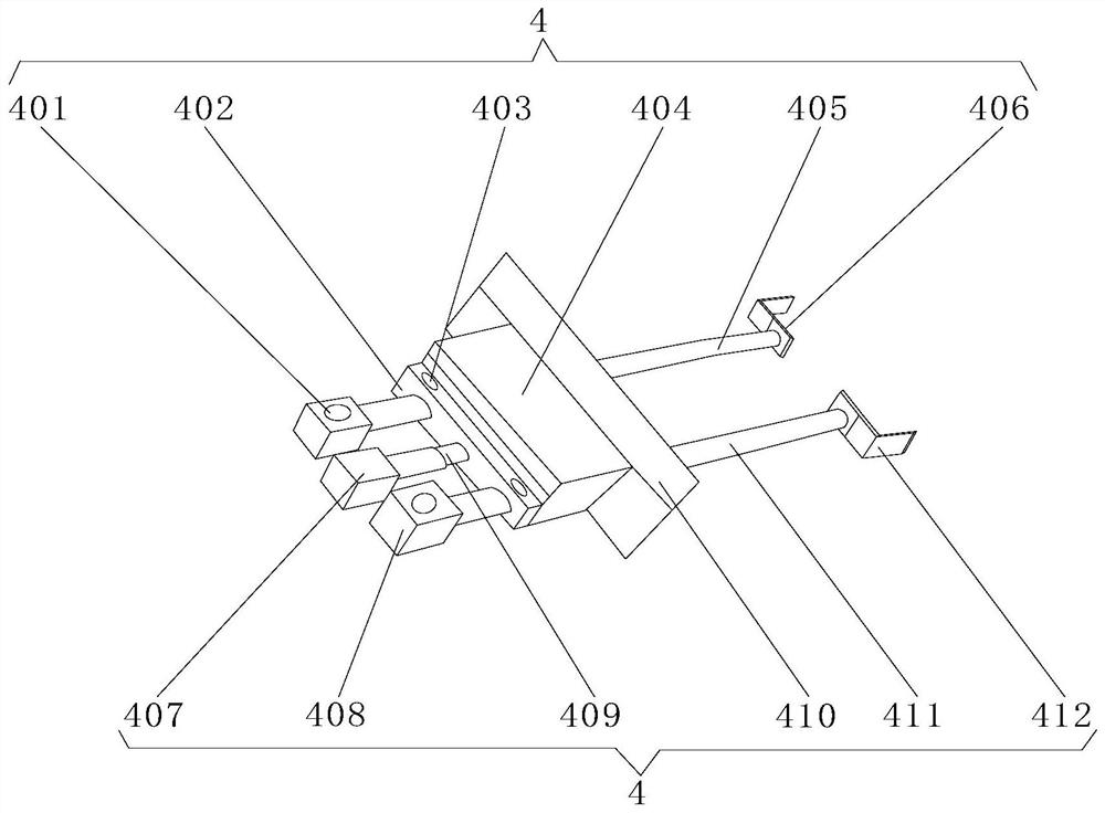
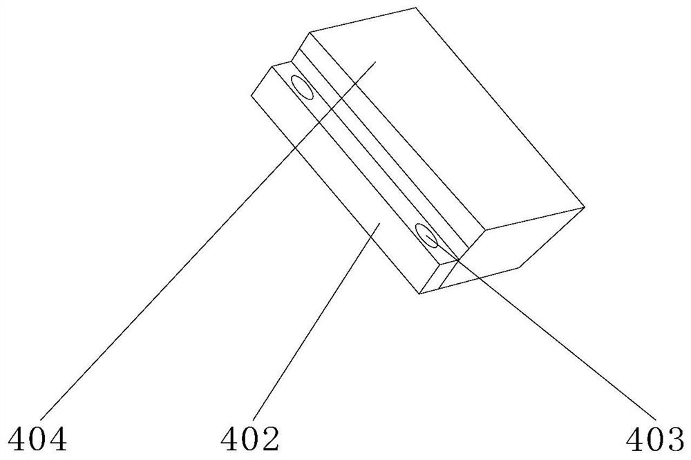
[0029] Example 1: as figure 2 , 3As shown, the slide rail telescopic material guide mechanism 4 includes No. 1 positioning seat 401, lubrication box 402, drip irrigation tank 403, sliding seat 404, No. 1 slide bar 405, first positioning member 406, fixed seat 407, No. 2 positioning seat 408, cylinder 409, push plate 410, No. 2 sliding rod 411, second positioning member 412, No. 1 sliding rod 405 is located on one side of No. 1 positioning seat 401, and first positioning member 406 is located on one side of No. 1 sliding rod 405 , the cylinder 409 is located on one side of the fixed seat 407, the second sliding rod 411 is located on the side of the second positioning seat 408, the second positioning member 412 is located on the side of the second sliding rod 411, and the lubrication box 402 is located on the side of the cylinder 409 , the drip irrigation tank 403 is located at the upper end of the lubrication box 402, the sliding seat 404 is located at one side of the lubrica...
Embodiment 2
[0030] Embodiment two: if Figure 4 , 5 As shown, the spiral cutting feeding mechanism 6 includes a material guide groove 601, a drive shaft 602, a screw rod 603, a cutting blade 604, an anti-skid pad 605, and a feeding screw rod 606. The drive shaft 602 is located on both sides of the screw rod 603, and the screw rod 603 is located on the In the inside of the material guide groove 601, the feeding screw 606 is positioned at the outer wall of the screw rod 603, the cutting blade 604 is positioned at one side of the feeding screw rod 606, the anti-skid pad 605 is positioned at the outer surface of the feeding screw rod 606, and the drive shaft 602 and the screw rod 603 are provided with Fixed connection seat, one side of the drive shaft 602 is fixedly connected with one side of the screw rod 603 through the fixed connection seat, super glue is arranged between the anti-skid pad 605 and the feeding screw 606, and the outer surface of the feeding screw 606 is connected by the sup...
Embodiment 3
[0031] Embodiment three: as Image 6 , 7 As shown, the positioning pin mechanism 10 includes a fixed support 1001, a positioning hole 1002, a pin 1003, a gasket 1004, a socket 1005, an adjustment rod 1006, and a fixed patch 1007. The socket 1005 is located at the front end of the fixed support 1001, and the latch 1003 is located Inside 1005, the adjusting rod 1006 is located at the front end of the latch 1003, the gasket 1004 is located on the outer surface of the latch 1003, the fixed patch 1007 is located on both sides of the fixed support 1001, and a welding seat is arranged between the fixed support 1001 and the socket 1005. The outer surface of the front end of the fixed support 1001 is fixedly connected to the outer surface of the rear end of the socket 1005 through a welding seat, and a fixing glue is arranged between the plug pin 1003 and the gasket 1004, and the outer surface of the bolt 1003 is connected to the inner surface of the gasket 1004 through the fixing glue...
PUM
 Abstract
Description
Claims
Application Information
 - R&D Engineer
- R&D Manager
- IP Professional
- Industry Leading Data Capabilities
- Powerful AI technology
- Patent DNA Extraction
Browse by: Latest US Patents, China's latest patents, Technical Efficacy Thesaurus, Application Domain, Technology Topic, Popular Technical Reports.
© 2024 PatSnap. All rights reserved.Legal|Privacy policy|Modern Slavery Act Transparency Statement|Sitemap|About US| Contact US: help@patsnap.com