
Slurry smoothing device and leveling machine

A slurry and screed technology, applied in the processing of building materials, roads, buildings, etc., can solve the problems of affecting the strength of concrete structures, and the joints are easy to become crack sources, and achieve the effect of improving the quality of troweling

Active Publication Date: 2021-08-31
GUANGDONG BOZHILIN ROBOT CO LTD
View PDF31 Cites 0 Cited by
  • Summary
  • Abstract
  • Description
  • Claims
  • Application Information

AI Technical Summary

Problems solved by technology

When the track-type leveling machine is used for leveling, it is easy to generate piles at the junction of two adjacent work areas. After the concrete is solidified, the joints where the piles are generated are likely to become the source of cracks, which seriously affects the strength of the concrete structure.

Method used


Image

  • Slurry smoothing device and leveling machine
  • Slurry smoothing device and leveling machine
  • Slurry smoothing device and leveling machine

Examples


Embodiment 1

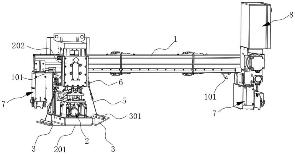
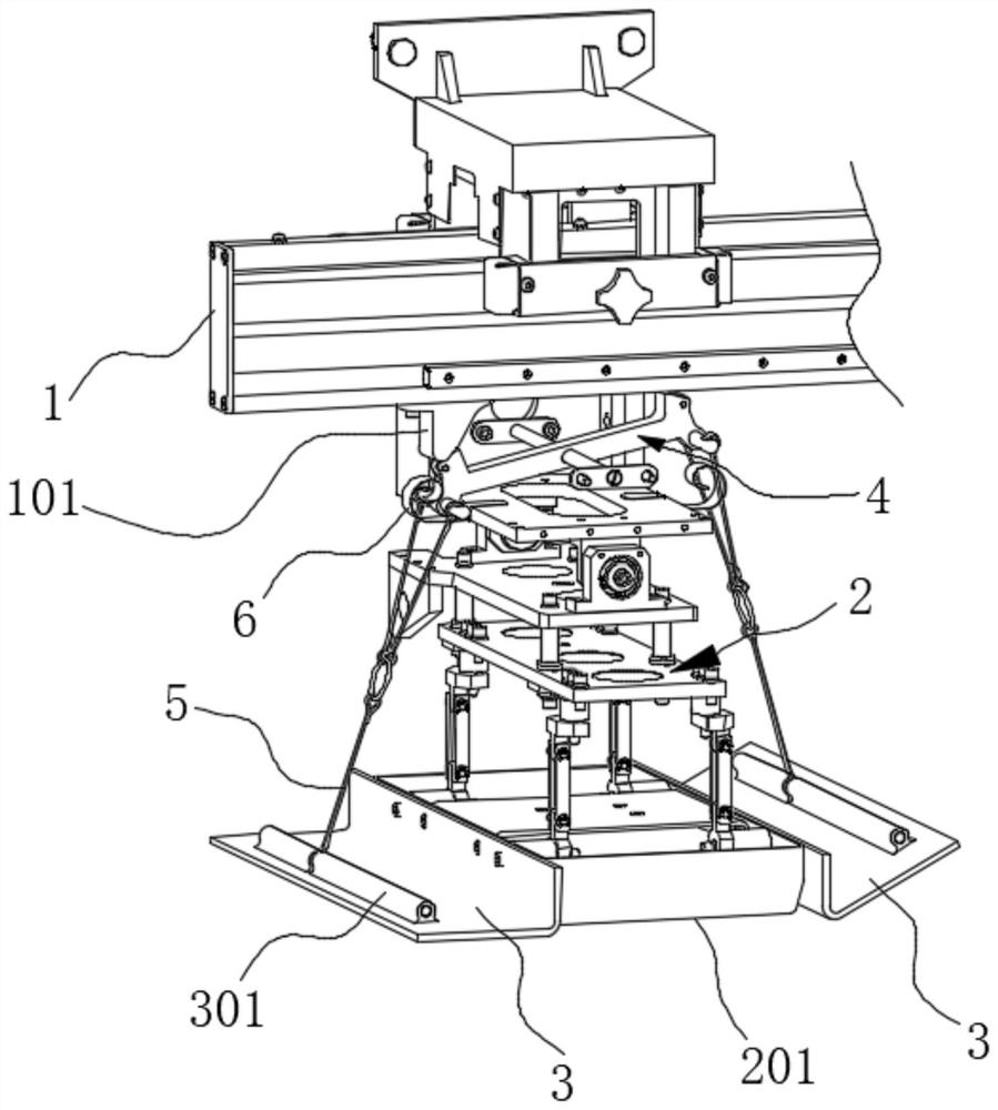
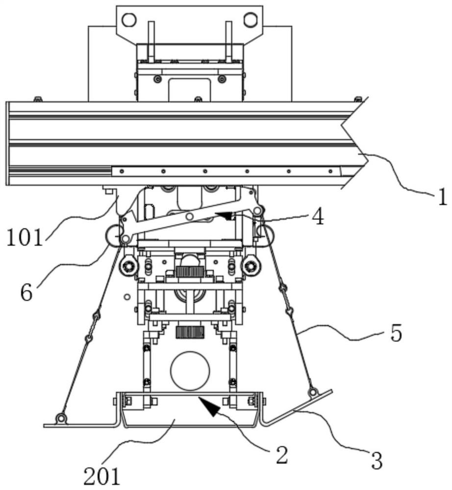
[0051] like Figure 1-Figure 6As shown, this embodiment provides a slurry leveling device for leveling the concrete floor of a residential building, including a beam 1, a leveling component 2 and a leveling component. Wherein, the leveling assembly 2 is slidably connected with the beam 1 and can slide along the beam 1. The leveling assembly 2 includes a screed plate 201 located at the bottom, and the leveling assembly is connected with the leveling assembly 2 and slides together. The leveling assembly includes a troweling plate 3. The screed plate 3 is arranged on the side of the screed plate 201 along the extension direction of the beam 1, and the width dimension of the screed plate 3 in the direction perpendicular to the extension direction of the beam 1 is larger than the width dimension of the screed plate 201 in this direction. When the screed 201 moves along the extension direction of the beam 1 and level the concrete, the trowel 3 arranged behind the screed 201 further ...

Embodiment 2

[0064] like figure 1 As shown, the present embodiment provides a leveling machine, including the slurry leveling device provided in Embodiment 1, and also includes a running mechanism 7 arranged at both ends of the beam 1 of the slurry leveling device, and the running mechanism 7 includes traveling wheels and A travel motor connected to the travel wheel in rotation, the travel motor is used to drive the travel wheel to rotate, so that the crossbeam 1 travels in the horizontal direction to adjust the working position.

[0065] Further, the leveling machine also includes an electric control assembly 8, which is electrically connected to the leveling drive motor and the traveling mechanism 7, and the electric control assembly 8 can be a centralized or distributed controller, for example, it can be a A single single-chip microcomputer, such as an STM32 single-chip microcomputer, can also be composed of distributed multi-block single-chip microcomputers. The control program can be ...


PUM


Abstract

The invention relates to the field of construction machinery, and discloses a slurry smoothing device and a leveling machine. The slurry leveling device includes a beam; the leveling component is slidably connected with the beam and can slide along the extension direction of the beam, and the leveling component includes a screed plate, which can abut against the slurry on the ground to The slurry is leveled during the sliding process in the extending direction; and the leveling component is connected with the leveling component and slides together, including a troweling plate capable of contacting the slurry on the ground, and the troweling plate is arranged on the extension of the leveling plate along the beam On the side of the direction, the width dimension of the screed plate in the direction perpendicular to the extension direction of the beam is larger than the width dimension of the screed plate in this direction. The invention can avoid stacking materials between adjacent working areas and improve smoothing quality.

Description

technical field [0001] The invention relates to the technical field of construction machinery, in particular to a slurry leveling device and a leveling machine. Background technique [0002] Concrete has high compressive strength, good durability, wide range of strength grades and low price, and is widely used as a structural material in various civil engineering and housing construction. When concrete is used for pavement, bridge deck, large square and house floor, it generally has higher requirements on the flatness of its surface. Therefore, many leveling technologies and equipment for concrete have emerged. [0003] Due to the relatively small area of ​​the residential floor, many floor embedded parts, and the small bearing capacity of the aluminum formwork or wood formwork used to support the concrete, the existing various leveling equipment is not suitable for the leveling of the floor. . However, if the size of the existing leveling machine is proportionally reduce...

Claims


Application Information

Patent Timeline
Patent Type & Authority Patents(China)
IPC IPC(8): E01C19/42E04G21/10
CPCE01C19/42E04G21/10
Inventor 阿斯嘎辛红伟台三鹏柴振徐明光
Owner GUANGDONG BOZHILIN ROBOT CO LTD
Learn More