Pit furnace and using method thereof

A well-type furnace and flange technology, which is applied to vertical furnaces, furnaces, furnace types, etc., can solve the problems of heavy workload, long maintenance time, and lower tank height, so as to prolong the service life and reduce the workload of modification , The effect of reducing the cost of equipment

Pending Publication Date: 2020-04-17
西安博莱炉业科技股份有限公司
View PDF0 Cites 0 Cited by
  • Summary
  • Abstract
  • Description
  • Claims
  • Application Information

AI Technical Summary

Problems solved by technology

[0002] The current common structure of the bowl furnace is composed of the top flange, the tank body and the head at the bottom of the tank body. The bottom head of the tank body is welded together with the tank body. The gas phase structure in the tank will cause the tank head to be corroded. After a long period of use, the bottom of the tank head will corrode and rot. When the corrosive substances deposited inside the head damage the head, the entire tank needs to be lifted out of the furnace. If the head needs to be replaced, it must be removed. The whole head is cut off, that is, the weld seam between the tank head and the tank body should be completely cut off, and a new head should be replaced and re-welded. If the weld seam is damaged during cutting, the height of the tank body will decrease, and the tank body needs to be increased. Height, this kind of structure requires a lot of work to replace, and the maintenance time is long, which affects production

Method used


Image

  • Pit furnace and using method thereof
  • Pit furnace and using method thereof

Examples


Embodiment 1

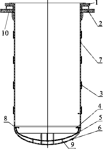
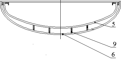
[0031] This embodiment provides a well-type furnace, including a tank body 7 and a tank body head 6, the tank body head 6 is fixed at the bottom of the tank body 7, and the inside of the tank body head 6 is provided with a lining head 5 , a limit device 8 is provided between the liner head 5 and the tank head 6, the liner head 5 is placed in the tank head 6 through a fixing frame 9, and the fixing frame 9 is fixed Inside the tank head 6 , a hoisting structure 4 is uniformly arranged in the circumferential direction of the lining head 5 .

[0032] The liner head 5 is placed inside the tank head 6 to protect the tank head 6. There is a specific limit device 8 between the liner head 5 and the tank head 6 to ensure that the liner Head 5 will not move.

[0033] Principle of the present invention:

[0034] In order to solve the problem that the gas phase structure in the tank body 7 will cause the tank head 6 to be corroded, the bottom of the tank head 6 will be corroded and rotte...

Embodiment 2

[0039] This embodiment provides a well-type furnace, including a tank body 7 and a tank body head 6, the tank body head 6 is fixed at the bottom of the tank body 7, and the inside of the tank body head 6 is provided with a lining head 5 , a limit device 8 is provided between the liner head 5 and the tank head 6, the liner head 5 is placed in the tank head 6 through a fixing frame 9, and the fixing frame 9 is fixed Inside the tank head 6 , a hoisting structure 4 is uniformly arranged in the circumferential direction of the lining head 5 .

[0040] The top of the tank body 7 is fixed with two tank body flanges, which are respectively the upper flange 1 of the tank body and the lower flange 2 of the tank body. The upper flange 1 of the tank body is provided with a sealing ring. A water jacket 10 is provided between the tank flanges.

[0041] The water jacket 10 is arranged between the two tank flanges to prevent the sealing ring from being deformed by heat and affecting the airt...

Embodiment 3

[0043] This embodiment provides a well-type furnace, including a tank body 7 and a tank body head 6, the tank body head 6 is fixed at the bottom of the tank body 7, and the inside of the tank body head 6 is provided with a lining head 5 , a limit device 8 is provided between the liner head 5 and the tank head 6, the liner head 5 is placed in the tank head 6 through a fixing frame 9, and the fixing frame 9 is fixed Inside the tank head 6 , a hoisting structure 4 is uniformly arranged in the circumferential direction of the lining head 5 .

[0044] A plurality of reinforcing ribs 3 are arranged on the outside of the tank body 7 from top to bottom. The distance between two adjacent reinforcing ribs 3 is 200-300mm, the thickness of the reinforcing ribs 3 is 8-10mm, and the width is 0.8-1m.

[0045] In order to ensure the strength of the tank body 7 while reducing the weight of the tank body itself, a plurality of reinforcing ribs 3 are added outside the tank body 7 .


PUM

PropertyMeasurementUnit
widthaaaaaaaaaa

Abstract

The invention provides a pit furnace and a using method thereof. The pit furnace comprises a tank body and a tank body seal head, the tank body seal head is fixedly arranged at the bottom of the tankbody, a lining seal head is arranged in the tank body seal head, a limiting device is arranged between the lining seal head and the tank body seal head, and the lining seal head is placed in the tankbody seal head through a fixing frame; and the fixing frame is fixedly arranged in the tank body seal head, and hoisting structures are evenly arranged in the circumferential direction of the lining seal head. The lining seal head is additionally arranged on the tank body seal head to perform anti-corrosion protection on the tank body seal head, when the lining seal head is corroded, only the lining seal head needs to be hoisted out of the tank body and replaced with a new lining seal head, the whole tank body does not need to be hoisted out, no influence on the tank body is caused, the tank body is not damaged, the modification workload is small, cost is low, the service life of the whole tank body is prolonged, and the equipment cost is reduced. A water jacket is arranged between two tank flanges, so that a sealing ring is prevented from being heated and deformed to influence the air tightness of the pit furnace.

Description

technical field [0001] The invention belongs to the technical field of well-type furnaces, and in particular relates to a well-type furnace and a using method thereof. Background technique [0002] The current common structure of the bowl furnace is composed of the top flange, the tank body and the head at the bottom of the tank body. The bottom head of the tank body is welded together with the tank body. The gas phase structure in the tank will cause the tank head to be corroded. After a long period of use, the bottom of the tank head will corrode and rot. When the corrosive substances deposited inside the head damage the head, the entire tank needs to be lifted out of the furnace. If the head needs to be replaced, it must be removed. The whole head is cut off, that is, the weld seam between the tank head and the tank body should be completely cut off, and a new head should be replaced and re-welded. If the weld seam is damaged during cutting, the height of the tank body wi...

Claims


Application Information

Patent Timeline
Patent Type & Authority Applications(China)
IPC IPC(8): F27B1/10
CPCF27B1/10
Inventor 鲁平瑞
Owner 西安博莱炉业科技股份有限公司
Why Eureka
Try Eureka