
Display panel, driving method thereof and display device

A technology of display panel and display area, applied in identification devices, static indicators, instruments, etc., can solve the problems of high screen-to-body ratio, large camera volume, and large frame area, so as to increase the screen-to-body ratio and improve the display. Contrast, improve reliability effect

Active Publication Date: 2020-04-17
WUHAN TIANMA MICRO ELECTRONICS CO LTD
View PDF6 Cites 4 Cited by
  • Summary
  • Abstract
  • Description
  • Claims
  • Application Information

AI Technical Summary

Problems solved by technology

[0003] The display panel in the electroluminescent display generally has a display area and a frame area. The frame area surrounds the display area. Optical devices such as cameras can be arranged in the frame area. Due to the large volume of the camera, the area occupied by the frame area is relatively large. large, resulting in greater restrictions in achieving high screen-to-body ratio and narrow bezel design

Method used


Image

  • Display panel, driving method thereof and display device
  • Display panel, driving method thereof and display device
  • Display panel, driving method thereof and display device

Examples


Embodiment Construction

[0034] Specific implementations of a display panel, a driving method thereof, and a display device provided by embodiments of the present invention will be described in detail below with reference to the accompanying drawings. It should be noted that the described embodiments are only some of the embodiments of the present invention, but not all of the embodiments. Based on the embodiments of the present invention, all other embodiments obtained by persons of ordinary skill in the art without making creative efforts belong to the protection scope of the present invention.

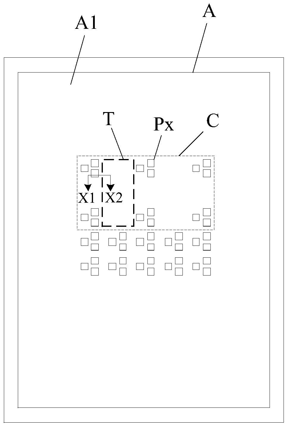
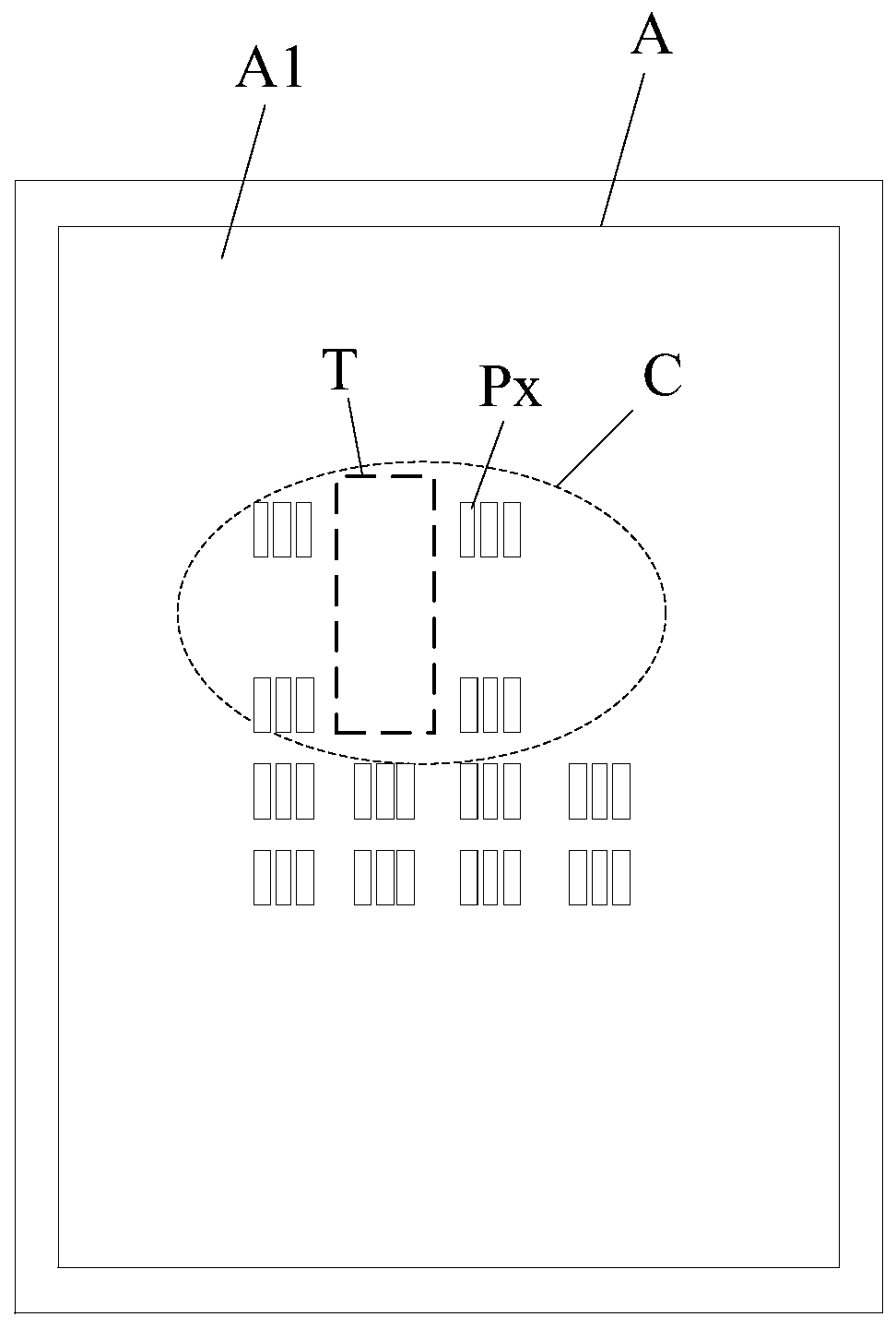
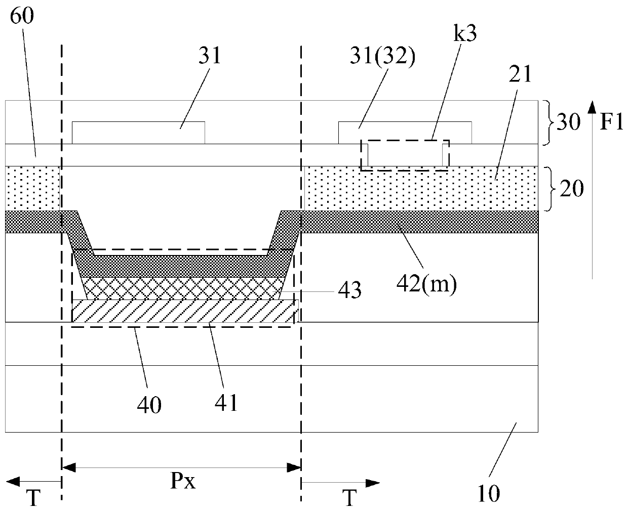
[0035] An embodiment of the present invention provides a display panel, such as Figure 1 to Figure 4 As shown, among them, figure 1 is a structural schematic diagram of a display panel, figure 2 is a structural schematic diagram of another display panel, image 3 for along figure 1 A cross-sectional view shown in the X1-X2 direction, Figure 4 for along figure 1 Another cross-sectional view shown in...


PUM


Abstract

The invention discloses a display panel, a driving method thereof and a display device. The display area comprises the photosensitive device setting area, and when a photosensitive device is arrangedin the photosensitive device setting area, the problem that the occupied area is large when the photosensitive device is arranged on a frame can be avoided, so that the frame can be arranged narrower,the screen-to-body ratio is increased, and the design of a narrow frame is realized. Moreover, when the photosensitive device is in a working state; therefore, a first structure has the first light transmittance; more light can be incident into the photosensitive device through the first structure, the performance of photosensitive device is improved, when the photosensitive device is in a non-working state and the display panel is in the display state, if the first structure has the second light transmittance, the amount of light penetrating through a light-transmitting area can be reduced through the first structure, and then the amount of light reflection of wires located in the light-transmitting area is reduced, so that the display contrast ratio is raised, the display effect is improved, and meanwhile, the reliability of the display device is improved.

Description

technical field [0001] The invention relates to the field of display technology, in particular to a display panel, a driving method thereof and a display device. Background technique [0002] An electroluminescent display is a self-luminous device that can display without a backlight. Compared with a liquid crystal display, this kind of display can be made thinner and thinner because it does not need a backlight, so it can be applied to various scenarios. [0003] The display panel in the electroluminescent display generally has a display area and a frame area. The frame area surrounds the display area. Optical devices such as cameras can be arranged in the frame area. Due to the large volume of the camera, the area occupied by the frame area is relatively large. Large, resulting in greater restrictions in achieving high screen-to-body ratio and narrow bezel design. [0004] Then, how to improve the high screen-to-body ratio of the display panel and realize the narrow frame...

Claims


Application Information

Patent Timeline
Patent Type & Authority Applications(China)
IPC IPC(8): H01L27/32G09F9/33G09G3/32
CPCG09F9/33G09G3/32H10K59/50H10K59/65H10K59/40H10K59/12H10K59/80522H10K59/873G06F3/0446G06F3/0412G06F3/0448H10K59/121G06F2203/04107H10K50/824H10K50/844H10K59/38
Inventor 张国峰王俊强
Owner WUHAN TIANMA MICRO ELECTRONICS CO LTD
Learn More