Jet engine

A jet engine and air technology, applied in machine/engine, jet propulsion device, gas turbine device, etc., can solve the problem of jet engine weight, achieve the effect of good mixing and shorten the structure space

Pending Publication Date: 2020-04-17
芬恩·亨德里克·冯韦斯特纳哈根
View PDF1 Cites 0 Cited by
  • Summary
  • Abstract
  • Description
  • Claims
  • Application Information

AI Technical Summary

Problems solved by technology

the jet engine is also relatively heavy due to multiple structural components

Method used


Image

  • Jet engine
  • Jet engine
  • Jet engine

Examples


Embodiment Construction

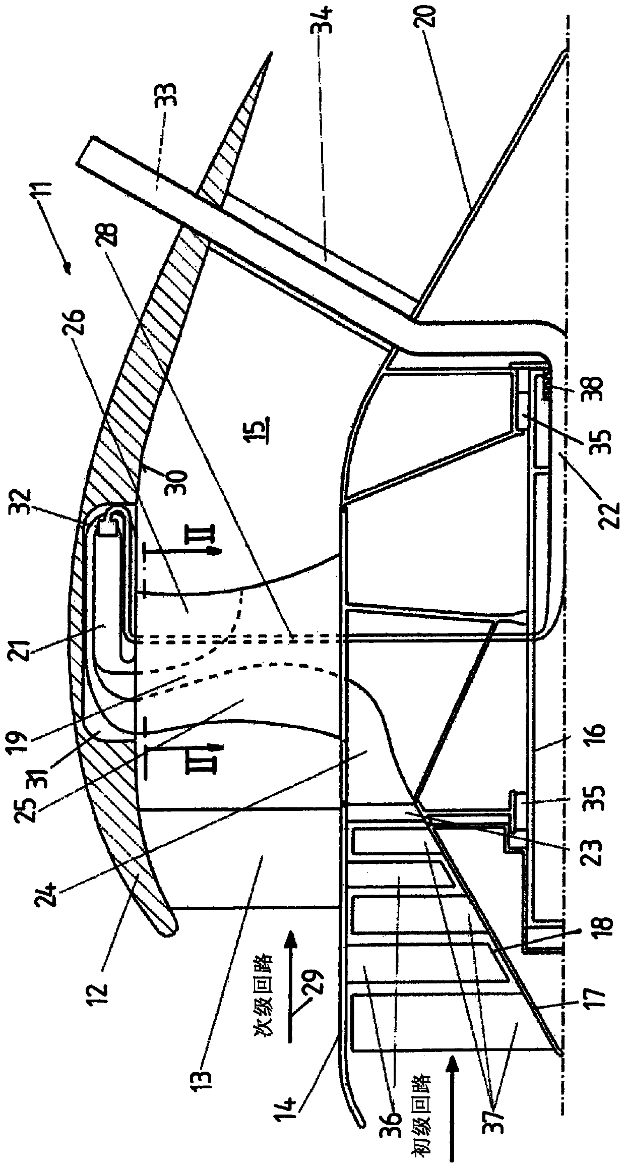
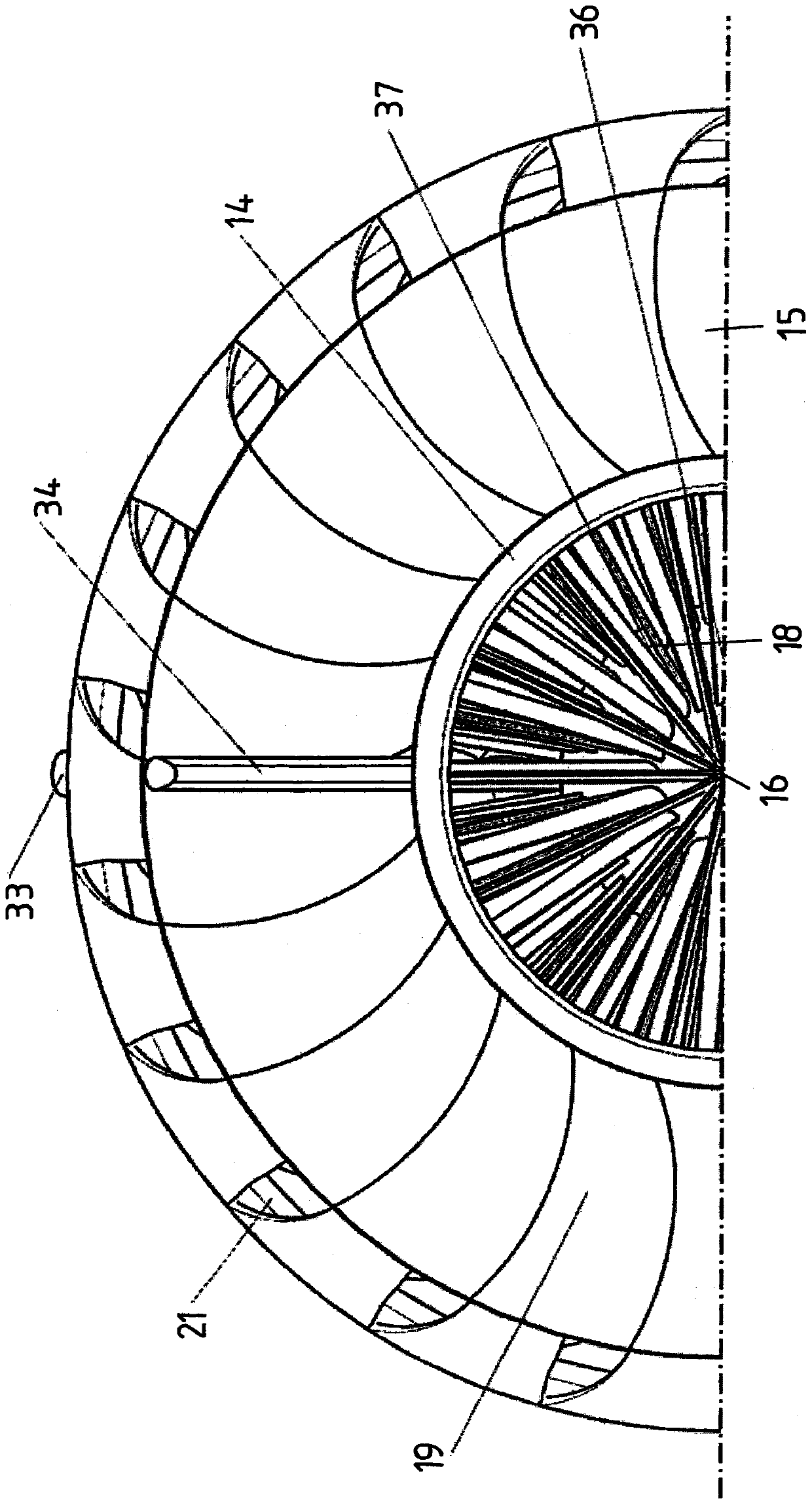
[0028] exist Figures 1 to 3 The jet engine shown exemplarily in has a stationary housing 11 comprising an outer housing wall 12 which is connected to an inner housing section 14 via radial supports 13 connect. Between the inner housing section 14 and the outer housing wall 12 there is an annular channel 15 in which the secondary flow is formed.

[0029] A spindle 16 is rotatably mounted in the inner housing section 14 . This main shaft 16 carries at its front end 17 an axial compressor 18 having a plurality of stages with stationary guide vanes 36 and blades 37 rotating with the main shaft.

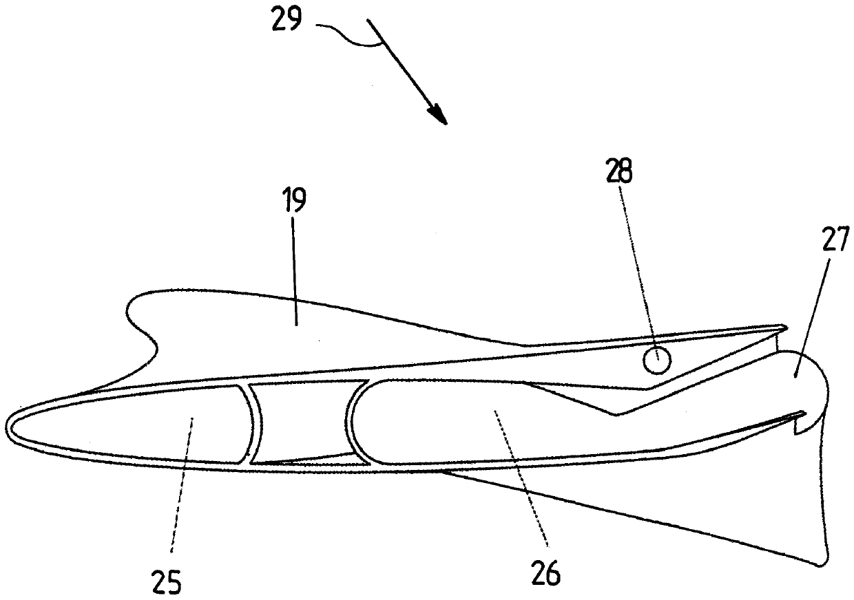
[0030] Furthermore, fan blades 19 of the fan are arranged on the main shaft 16 . Thus, the fan blades 19 turn in the same direction and at the same rotational speed as the compressor stages. In principle, gears or coaxial shafts can also be present in order to be able to achieve different directions of rotation or rotational speeds of the fan and compressor.

[0031] further back in...


PUM


Abstract

The invention relates to a jet engine which has a stationary housing in which a primary flow is formed. The inflowing air in the primary flow is burned in at least one combustion chamber, and in the housing a secondary flow is formed, and the inflowing air in the secondary flow is accelerated by a fan and is discharged at the outlet cone of the housing together with the exhaust gas from the combustion chamber. The fan is mounted on a main shaft for rotation about an axis and has a plurality of fan blades which extend substantially radially. According to the invention, at least one fan blade orthe plurality of the fan blades or all of the fan blades have at least one air inlet channel for the primary flow, the air inlet channel conducts the air of the primary flow through the fan blade tothe combustion chamber, and at least one fan blade or the plurality of the fan blades or all of the fan blades each have an outlet channel having an outlet opening oriented at least partly axially andat least partly tangentially, thereby feeding the exhaust gas from the combustion chambers to the accelerated air of the secondary flow. The mixture of air and exhaust gas is exhausted at the outletcone of the housing of the jet engine so as to generate the thrust.

Description

technical field [0001] The invention relates to a jet engine having a stationary housing, in which a primary flow is formed, in which air flowing in is combusted in at least one combustion chamber, and in which a secondary flow is formed, in which The incoming air in the secondary flow is accelerated and ejected at the outlet cone of the housing together with the exhaust air from the combustion chamber by a fan which is rotatably mounted on the main shaft and has a plurality of substantially radial Extended fan blades. Background technique [0002] Jet engines of this type are known generally and in different embodiments. A possible embodiment is a turbofan engine in which the secondary flow surrounds the primary flow on the outside. This often involves an arrangement in which the fan is first arranged on the shaft in the axial direction from the front to the rear. Behind the fan, the incoming air accelerated by the fan is divided into an inner primary flow and an outer s...

Claims


Application Information

Patent Timeline
Patent Type & Authority Applications(China)
IPC IPC(8): F02K3/068F02C3/09F02C3/14F02C3/16
CPCF02K3/068F02C3/09F02C3/145F02C3/16F02C3/165
Inventor 芬恩·舍宁德拉甘·科祖洛维奇
Owner 芬恩·亨德里克·冯韦斯特纳哈根
Why Eureka
Try Eureka