Rotational multi-degree-of-freedom motion generation platform

A technology with degrees of freedom and motion, applied in the direction of non-electric variable control, mechanical oscillation control, instruments, etc., can solve the problems of inconvenient driving force and driving force control and adjustment, inability to meet precise control output vibration, complex structure installation, etc., to achieve The effect of simple structure, light weight and high driving efficiency

Active Publication Date: 2018-10-12
伶机(上海)驱动技术中心(有限合伙)
View PDF6 Cites 0 Cited by
  • Summary
  • Abstract
  • Description
  • Claims
  • Application Information

AI Technical Summary

Problems solved by technology

[0003] 1. Insufficient driving force;
[0004] 2. Complex structure installation;
[0005] 3. It is not convenient to adjust the driving force and driving force control according to the needs;
[0006] 4. Poor drive accuracy;
[0007] Due to the above defects, the existing oscillating and rotating platforms usually cannot meet the demand for precise control of the output vibration

Method used


Image

  • Rotational multi-degree-of-freedom motion generation platform
  • Rotational multi-degree-of-freedom motion generation platform
  • Rotational multi-degree-of-freedom motion generation platform

Examples


Embodiment 1

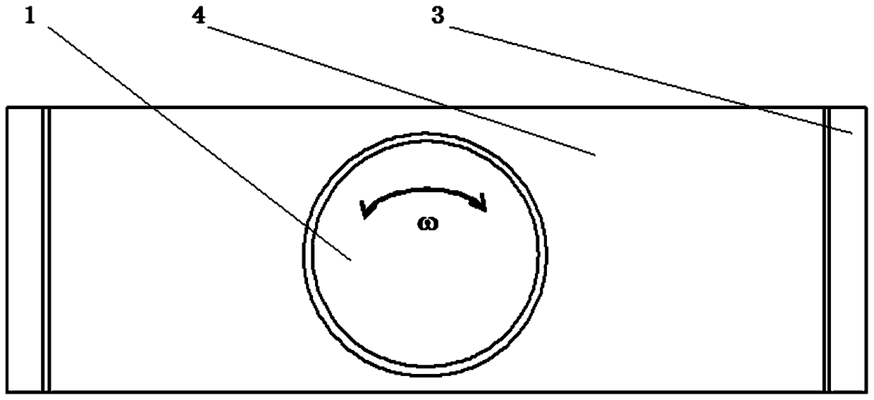
[0048] Such as figure 1 As shown, this embodiment provides a swinging multi-degree-of-freedom motion generation platform, including: a structural frame body, a cover structure, a rotating component, a transmission component, and a swing component; the cover structure is arranged on the top of the structural frame body , and form a structural shell with the structural frame body; the rotating parts and transmission parts are respectively embedded in the cover structure; the swinging parts are arranged inside the structural shell; wherein:

[0049] The rotating part is drivingly connected with the transmission part;

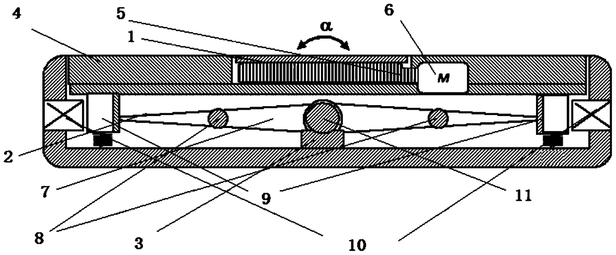
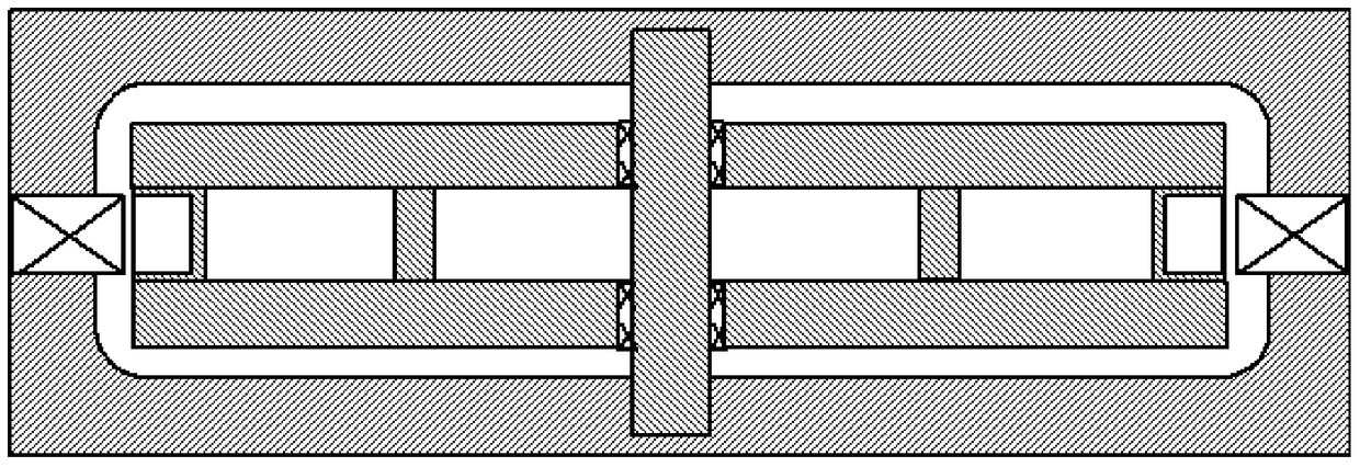
[0050] Such as figure 2 with image 3 As shown, the swinging part includes a set of magnetic force generating parts and electromagnetic direct drive parts, a swing beam and a swing beam supporting part; a magnetic control loop is formed between the magnetic field force generating part and the electromagnetic direct drive part, and the electromagnetic direct driv...

Embodiment 2

[0073] Embodiment 2 is a modification example of Embodiment 1.

[0074] Such as Figure 4 As shown, on the basis of embodiment 1, the present embodiment differs from embodiment 1 in that:

[0075] The magnetic field force generation part and the electromagnetic direct drive part are multiple groups, and the magnetic field force generation part in the multi-group magnetic field force generation part and the electromagnetic direct drive part is installed on the structural frame body, and the multi-group magnetic field force generation part and the electromagnetic direct drive part Corresponding to the magnetic field force generating part in the driving connection is connected on the swing beam.

Embodiment 3

[0077] Embodiment 3 is a modification example of Embodiment 1.

[0078] On the basis of embodiment 1, this embodiment differs from embodiment 1 in that:

[0079] The swing supporting part adopts ball bearings, such as Figure 5 with Image 6 As shown, the ball bearing can rotate in both directions.


PUM


Abstract

The invention provides a swing and rotation multi-degree-of-freedom motion generating platform. The swing and rotation multi-degree-of-freedom motion generating platform includes a structural frame, a cover plate structure, a rotation component, a transmission component and a swing component; the cover plate structure is arranged at the top of the structural frame; the cover plate structure and the structural frame form a structural shell; the rotation component and the transmission component are respectively embedded in the cover plate structure; the swing component is arranged in the structural shell; the rotation component is in driving connection with the transmission component; the swing component comprises at least one set of magnetic field force generating component and electromagnetic direct driving component, a swing beam and a swing beam supporting component; an magnetic control loop is formed between the magnetic field force generating components and the electromagnetic direct driving components; the electromagnetic direct driving components move in a reciprocating manner under the action of the magnetic forces of the magnetic field force generating components; the swing beam is in driving connection with the electromagnetic direct driving components; and the swing beam supporting component is supported at the center position of the swing beam. The swing and rotation multi-degree-of-freedom motion generating platform of the invention has the advantages of simple structure and light weight, and can satisfy requirement of broadband response and precise control of output vibration.

Description

technical field [0001] The invention relates to the technical field of magnetic drive, in particular to a swinging multi-degree-of-freedom motion generating platform. Background technique [0002] The oscillating and rotating platforms can be used in many fields, such as the oscillating test of the workpiece, human body movement equipment, etc. Existing oscillating and rotating test devices or human body movement equipment are usually controlled by motors. This structure leads to the following defects in the existing oscillating and rotating platforms: [0003] 1. Insufficient driving force; [0004] 2. Complex structure installation; [0005] 3. It is not convenient to adjust the driving force and driving force control according to the needs; [0006] 4. Poor drive accuracy; [0007] Due to the above defects, the existing oscillating and rotating platforms are generally unable to meet the demand for precise control of the output vibration. Contents of the invention ...

Claims


Application Information

Patent Timeline
Patent Type & Authority Patents(China)
IPC IPC(8): G05D3/00G05D19/02
Inventor 杨斌堂
Owner 伶机(上海)驱动技术中心(有限合伙)
Why Eureka
Try Eureka