MEMS device for lens barrel positioning

A lens barrel and axis positioning technology, which is applied in the direction of the mechanism, installation, and mechanical equipment that generates mechanical power.

Active Publication Date: 2021-02-09
NINGBO SUNNY OPOTECH CO LTD +1
View PDF2 Cites 0 Cited by
  • Summary
  • Abstract
  • Description
  • Claims
  • Application Information

AI Technical Summary

Problems solved by technology

The adoption of this technology will drive the redesign of current optics; therefore its penetration rate is low

Method used

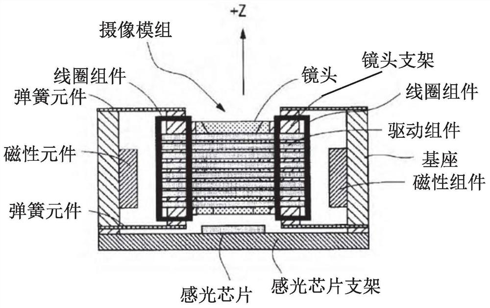
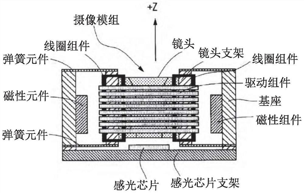
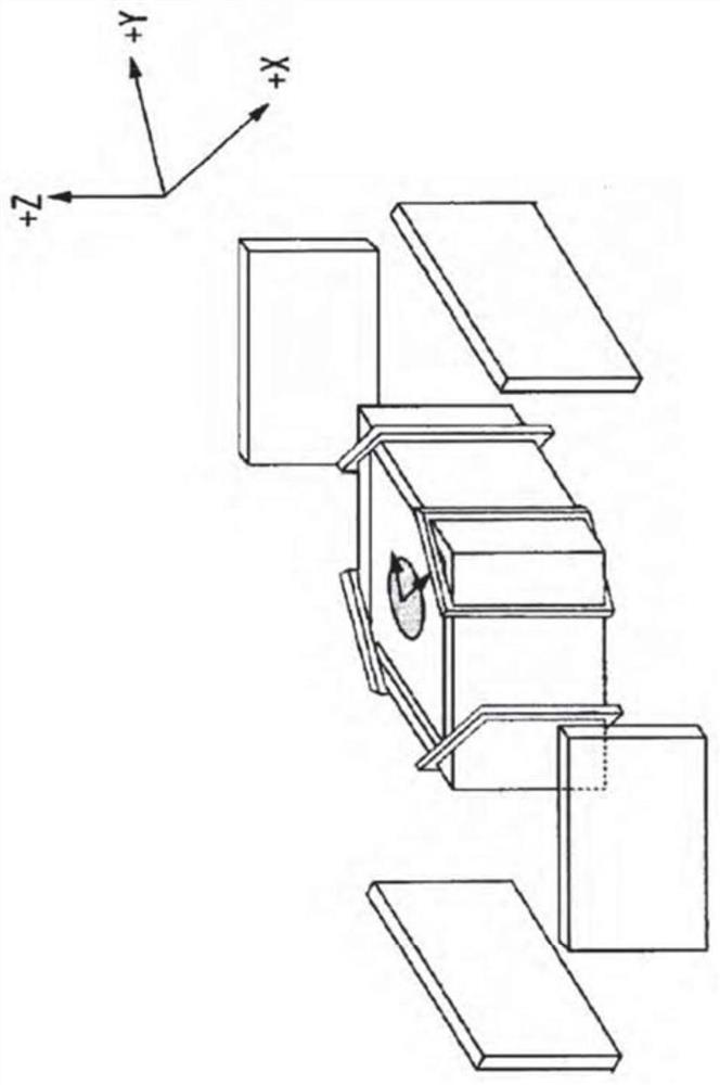

Image

  • MEMS device for lens barrel positioning
  • MEMS device for lens barrel positioning
  • MEMS device for lens barrel positioning

Examples


Embodiment Construction

[0062] The following description serves to disclose the present invention to enable those skilled in the art to carry out the present invention. The preferred embodiments described below are only examples, and those skilled in the art can devise other obvious variations. The basic principles of the present invention defined in the following description can be applied to other embodiments, variations, improvements, equivalents and other technical solutions without departing from the spirit and scope of the present invention.

[0063] Those skilled in the art should understand that in the disclosure of the present invention, the terms "vertical", "transverse", "upper", "lower", "front", "rear", "left", "right", " The orientation or positional relationship indicated by "vertical", "horizontal", "top", "bottom", "inner", "outer", etc. is based on the orientation or positional relationship shown in the drawings, which are only for the convenience of describing the present invention...


PUM


Abstract

A micro-electromechanical system (MEMS), which uses a thermal micro-actuator (31) to position a lens barrel (20) on a smart device, such as a camera module of a mobile phone. The micro-driver extends radially relative to a lens barrel, and each micro-driver can be bent by heat. The control unit (32) includes a heating circuit (321) operatively connected to the micro-drives to controllably apply thermal energy to each of the micro-drives, wherein each micro-drive is correspondingly bent to face a base (10) The lens barrel is moved, thereby controlling the three-axis positioning of the lens barrel. The operation of the microdrive is not affected by changes in ambient temperature.

Description

technical field [0001] The present invention relates to a camera module, wherein the camera module is usually mounted on a smart device camera, wherein a lens barrel is positioned on a camera module to obtain high-quality images in image collection such as photography and videography. In particular, the present invention relates to a thermally driven micro-driver, wherein the micro-driver can realize autofocus and prevent hand shake from affecting the camera module of the smart device. Background technique [0002] Autofocus is often used in cameras on the market. It uses linear actuators to position lenses within a camera to move the focus of the lenses to an image sensor. If the lenses are not in focus on the image sensor surface, blurry images will result. Due to the miniaturization challenges of linear actuators, this technology is difficult to apply to smartphone camera modules. [0003] It has been found that voice coil motors (VCMs) and microelectromechanical syste...

Claims


Application Information

Patent Timeline
Patent Type & Authority Patents(China)
IPC IPC(8): G02B27/64G02B7/09G02B7/08F03G7/06F03G7/00G03B3/10G03B30/00
CPCF03G7/00F03G7/06G02B7/08G02B27/646F03G7/0612F03G7/0121G02B7/09
Inventor 张玉文林成义陈振宇刘义强朱传贵
Owner NINGBO SUNNY OPOTECH CO LTD
Why Eureka
Try Eureka