Optical film having improved contrast ratio, polarizing plate including same, and liquid crystal display device including same

A technology of optical film and contrast ratio, which is applied in the field of optical film and can solve problems such as degradation

Active Publication Date: 2020-04-17
SAMSUNG SDI CO LTD
View PDF5 Cites 4 Cited by
  • Summary
  • Abstract
  • Description
  • Claims
  • Application Information

AI Technical Summary

Problems solved by technology

[0005] However, in the structure in which the anti-glare film is stacked on the contrast-ratio-improving optical film, the improvement of visibility by the co

Method used


Image

  • Optical film having improved contrast ratio, polarizing plate including same, and liquid crystal display device including same
  • Optical film having improved contrast ratio, polarizing plate including same, and liquid crystal display device including same
  • Optical film having improved contrast ratio, polarizing plate including same, and liquid crystal display device including same

Examples


preparation example 1

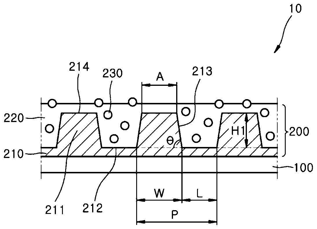
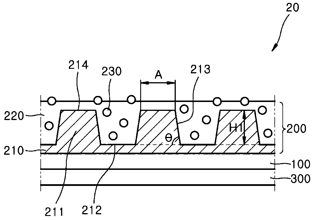
[0134] Preparation Example 1: Preparation of the composition for the patterned layer

[0135]By adding 73 parts by weight of a solvent-free zirconia-containing solution HR-10-1 (Nippon Shokubai Co., Ltd.), the average particle diameter (D50) of zirconia: 11 nm, containing dispersed in acrylic benzyl 80% by weight of high refractive index compound of zirconia in ester, refractive index: 1.67) mixed with 22 parts by weight of trimethylpropane triacrylate, followed by 4.5 parts by weight of starter (TPO LG, India Globalization Capital Co., Ltd. (IGC Co., Ltd.)) and 0.5 parts by weight of a release agent (BYK 3500) were added to the mixture to prepare a composition for a patterned layer. The composition used for the patterned layer had a refractive index of 1.60. In the composition for the patterned layer, zirconia was present in an amount of 51% by weight in terms of solid content.

preparation example 2

[0136] Preparation Example 2: Preparation of Composition for Gap Filling Layer

[0137] 23 parts by weight of a photocurable compound (UP111, ENTIS Co., Ltd, solid content: 70% by weight, solvent: PGME (propylene glycol methyl ether)), 8.4 parts by weight of SR833S (Sartomer Co., Ltd. (SartomerCo., Ltd.)), 8 parts by weight of HDDA (ENTIS Co., Ltd.), 46 parts by weight of propylene glycol monomethyl ether acetate (propylene glycol monomethylether acetate; PGMEA) and 12 parts by weight of methyl isobutyl Base ketone (MIBK) was mixed and stirred. After the stirring was completed, 1.15 parts by weight of initiator (Omnirad 184, India Globalization Capital Limited), 0.03 parts by weight of UV reactive silicone additive (UV3500), 0.07 parts by weight of dispersant (Disperbyk-2163, BYK Co., Ltd.) and 0.05 parts by weight of an anti-fingerprint agent (KY1203, Shin-Etsu Co., Ltd.) were added to the mixture, whereby a solution was prepared.

[0138] Organic particles (MSX-105, refrac...

preparation example 3

[0139] Preparation Example 3: Preparation of Composition for Gap Filling Layer

[0140] A solution was prepared by the same method as in Preparation Example 2.

[0141] Organic particles (MSX-2H, refractive index: 1.495, polymethyl methacrylate particles, average particle diameter (D50): 2.7 µm, intermediate dispersion particles, Sekisui Co., Ltd.) were mixed with the solution, thereby preparing Fill layer solution. The composition for the gap-fill layer contained 6% by weight of organic particles in terms of solid content.


PUM

PropertyMeasurementUnit
Average particle diameteraaaaaaaaaa

Abstract

Disclosed is an invention related to an optical film having an improved contrast ratio, a polarizing plate including same, and a liquid crystal display device including same. The optical film having an improved contrast ratio includes a protection layer and a pattern layer disposed on the protection layer, the pattern layer includes an embossed optical pattern on one surface thereof and a patternpart including a flat portion between the embossed optical pattern and another adjacent embossed optical pattern, the embossed optical pattern has a base angle (theta) of about 55 degrees to about 90degrees, and the pattern part satisfies equation 1.The optical film having the improved contrast ratio further includes a gap fill layer that directly contacts the one surface of the pattern layer. (Equation 1 is defined in the specification.)

Description

technical field [0001] The present invention relates to an optical film for improving contrast ratio, a polarizing plate including the optical film, and a liquid crystal display device including the above. Background technique [0002] The liquid crystal display device operates to emit light through two polarizing plates after receiving light from the backlight unit. Therefore, in terms of color quality, contrast ratio, and viewing angle, the screen of the liquid crystal display device has lower characteristics in its lateral direction than in its frontal direction. [0003] In order to improve the color quality, contrast ratio, and viewing angle at the side of the liquid crystal display device, various attempts have been made by modifying the liquid crystal panel or liquid crystal structure. However, improvement by modifying the liquid crystal panel is limited and requires complicated processes. In the VA type liquid crystal display device, the disadvantage of a narrower ...

Claims


Application Information

Patent Timeline
IPC IPC(8): G02B5/02G02B5/30G02F1/1335C08L25/04
CPCG02B5/0215G02B5/0226G02B5/30G02F1/133528C08L25/04
Inventor 赵成昕闵景俊韩智映金旻成朴世铉吴釜根郑伍溶
Owner SAMSUNG SDI CO LTD
Why Eureka
Try Eureka