A cleaning device for floor heating pipeline installation

A pipeline installation and cleaning device technology, which is applied in the direction of cleaning hollow objects, cleaning methods and utensils, and drying solid materials without heating. It can solve the problems of inability to clean the intensity adjustment and poor cleaning effect of floor heating pipes, so as to prevent wear and tear. Effect

Active Publication Date: 2021-11-09
诸暨市富华机械有限公司
View PDF10 Cites 0 Cited by
  • Summary
  • Abstract
  • Description
  • Claims
  • Application Information

AI Technical Summary

Problems solved by technology

A floor heating pipeline cleaning device in the above-mentioned patent has the following disadvantages: the existing device cannot adjust the cleaning intensity when cleaning the floor heating pipeline. The cleaning effect of the device on the floor heating pipe is poor due to insufficient

Method used


Image

  • A cleaning device for floor heating pipeline installation
  • A cleaning device for floor heating pipeline installation
  • A cleaning device for floor heating pipeline installation

Examples


Embodiment 1

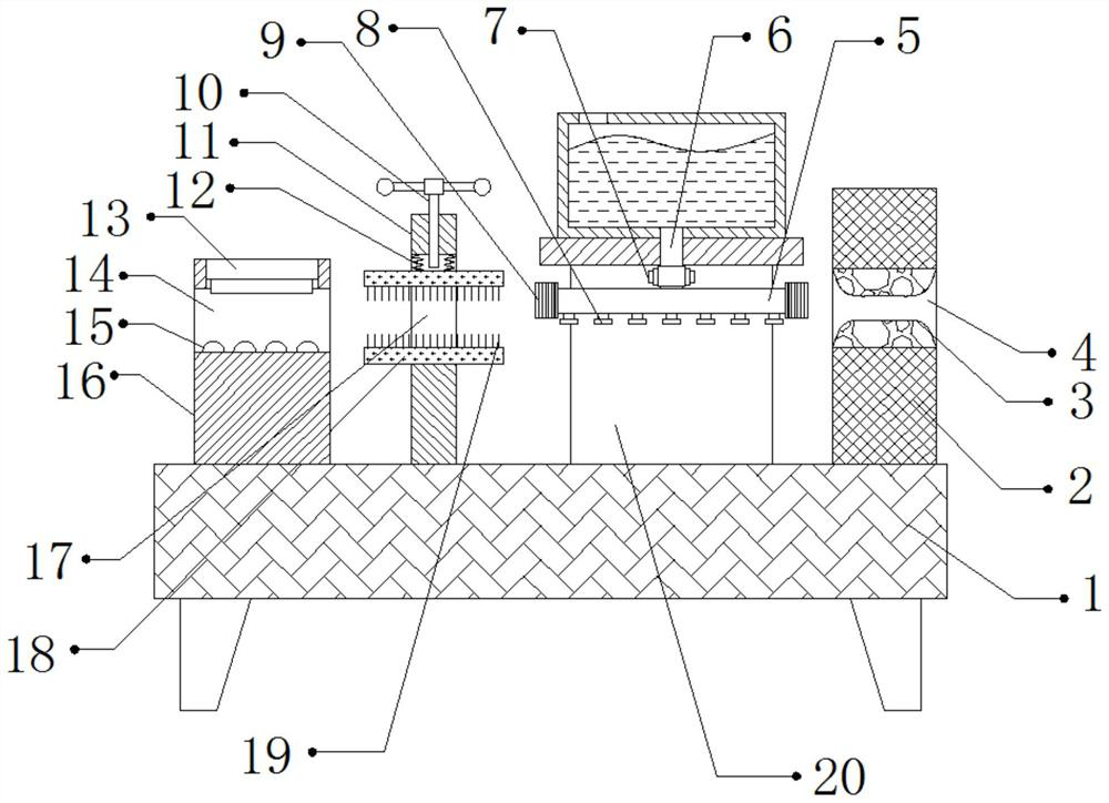
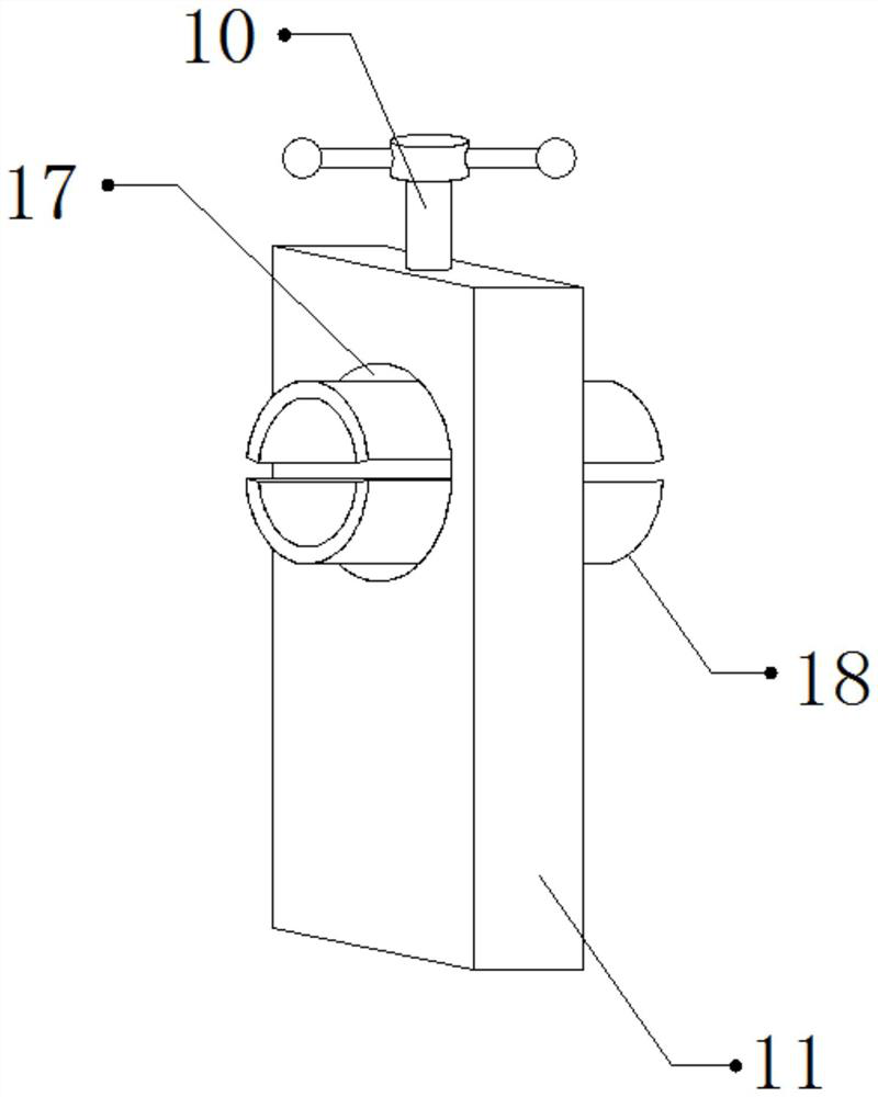
[0026] refer to Figure 1-3 , a cleaning device for installing floor heating pipes, comprising a fixed base 1, one side of the top outer wall of the fixed base 1 is connected with a fixed plate 11 by bolts, and one side outer wall of the fixed plate 11 is provided with a fixed opening 17, and the inner wall of the top of the fixed opening 17 Both sides of the spring 12 are connected with springs 12 by bolts, and the bottom outer walls of the two springs 12 and the bottom inner walls of the fixed opening 17 are connected with splints 18 by bolts, and the outer walls on the opposite side of the two splints 18 are all connected by bolts. Brush 19, the top inner wall of fixed opening 17 is provided with threaded hole, and the inner wall of threaded hole is threadedly connected with threaded rod 10, and one side of fixed base 1 top outer wall is connected with fixed frame 20 by bolt, and the top outer wall of fixed frame 20 passes through Bolts are connected with a liquid storage t...

Embodiment 2

[0034] refer to Figure 4 , a cleaning device for installing floor heating pipes. Compared with Embodiment 1, in this embodiment, vibration motors 21 are connected to both sides of the bottom outer wall of the fixing seat 1 through bolts, and the vibration of the vibration motor 21 can drive the floor heating pipes to shake. Thereby, the water stain adhering to the surface of the floor heating pipe can be dried, and in addition, the stain can be discharged from the floor heating pipe through vibration.

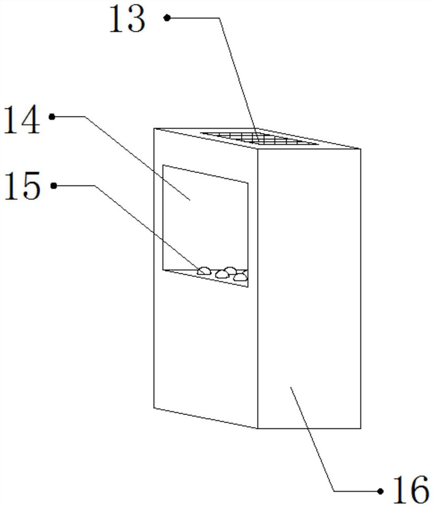
[0035]Working principle: When in use, one end of the floor heating pipe to be cleaned passes through the through port 14, the fixed port 17 and the rectangular port 4 respectively, and the dust adhering to the surface of the floor heating pipe can be preliminarily treated by the fan 13, and the dust adhered to the surface of the floor heating pipe can be preliminarily treated by the ball 15. It can reduce the friction between the floor heating pipe and the port 14, prevent the...


PUM


Abstract

The invention discloses a cleaning device for floor heating pipeline installation, which comprises a fixing seat, a fixing plate is fixed on one side of the top outer wall of the fixing seat, and a fixing port is opened on one side of the outer wall of the fixing plate, and a fixing port is opened on the top inner wall of the fixing port. Springs are fixed on both sides, and splints are fixed on the bottom outer wall of the two springs and the bottom inner wall of the fixing port, and cleaning brushes are fixed on the opposite side of the outer wall of the two splints, and the top inner wall of the fixing port is provided with threads hole, and the inner wall of the threaded hole is threadedly connected with a threaded rod, one side of the top outer wall of the fixing seat is fixed with a fixing frame, and the top outer wall of the fixing frame is fixed with a liquid storage tank. The invention can prevent the cleaning effect of the device on the floor heating pipeline from being poor due to insufficient cleaning force of the device on the floor heating pipeline, and can prevent the surface of the floor heating pipeline from being worn due to high friction, thereby affecting the use of the floor heating pipeline. Dry the water stains adhering to the surface of the floor heating pipe.

Description

technical field [0001] The invention relates to the technical field of floor heating pipes, in particular to a cleaning device for installing floor heating pipes. Background technique [0002] Floor heating is the abbreviation of radiant floor heating. It uses the whole ground as a radiator, and heats the whole ground evenly through the heat medium in the radiant layer of the floor. It uses the heat storage of the ground itself and the law of upward radiation of heat to conduct from bottom to top to achieve For the purpose of heating, when the floor heating pipes are processed, the floor heating pipes need to be cleaned by a cleaning device. [0003] After searching, the Chinese patent authorization number is CN208825123U, which discloses a floor heating pipe cleaning device, including a cleaning pool. The middle part of the inner cavity of the cleaning pool is fixed with a mounting ring through the legs, and the mounting ring is along the width of the cleaning pool. Direct...

Claims


Application Information

Patent Timeline
Patent Type & Authority Patents(China)
IPC IPC(8): B08B9/023B08B13/00F26B5/00
CPCB08B9/023B08B13/00F26B5/00
Inventor 陈旭东
Owner 诸暨市富华机械有限公司
Why Eureka
Try Eureka