Bearing automatic finish forging single production line

A production line and precision forging technology, which is applied in the field of bearing processing, can solve the problems of burrs easily produced by sleeve punching products, the inability to carry out automatic production, uneven temperature of the production line, etc., and achieve the effect of convenient automatic operation, fast speed and improved product quality

Inactive Publication Date: 2020-04-21
浙江赛赛轴承有限公司
View PDF6 Cites 4 Cited by
  • Summary
  • Abstract
  • Description
  • Claims
  • Application Information

AI Technical Summary

Problems solved by technology

[0003] However, there are still the following disadvantages when using the existing technology in production. First, multiple equipments are needed when using the way of sleeve punching to produce, and the long production line will easily lead to uneven temperature, and the sleeve punching product is easy to produce burrs , The material of the inner ring is loose, which seriously affects the product quality
Second, in the prior art, in the punching forming step, only the upper die moves for punching forming, which requires the blank to be placed in the lower die groove for fixed forming. Such a production method requires manual processing after punching and forming. Unloading, unable to carry out automated production, reducing production speed
Third, in the prior art, water is used to lubricate and cool the head of the punching machine, and the friction force of the water is relatively large, which may easily cause the blank to be lifted when the punching machine is raised, thus affecting the processing process

Method used


Image

  • Bearing automatic finish forging single production line
  • Bearing automatic finish forging single production line
  • Bearing automatic finish forging single production line

Examples


Embodiment Construction

[0022] In order to make the object, technical solution and advantages of the present invention clearer, the present invention will be further described in detail below in conjunction with the accompanying drawings and embodiments. It should be understood that the specific embodiments described here are only used to explain the present invention, not to limit the present invention.

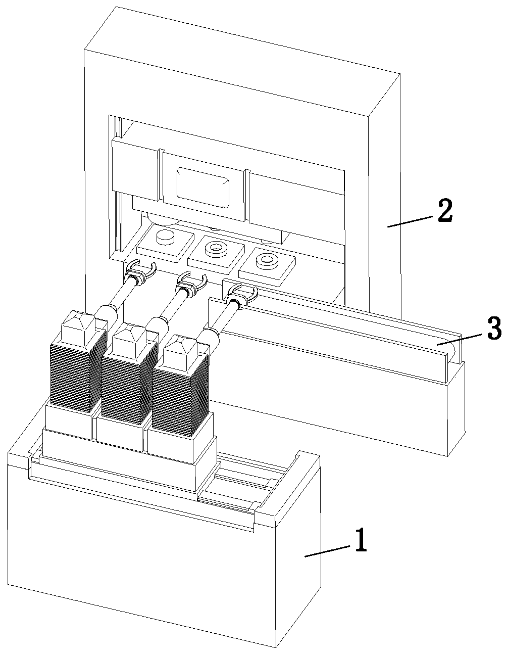
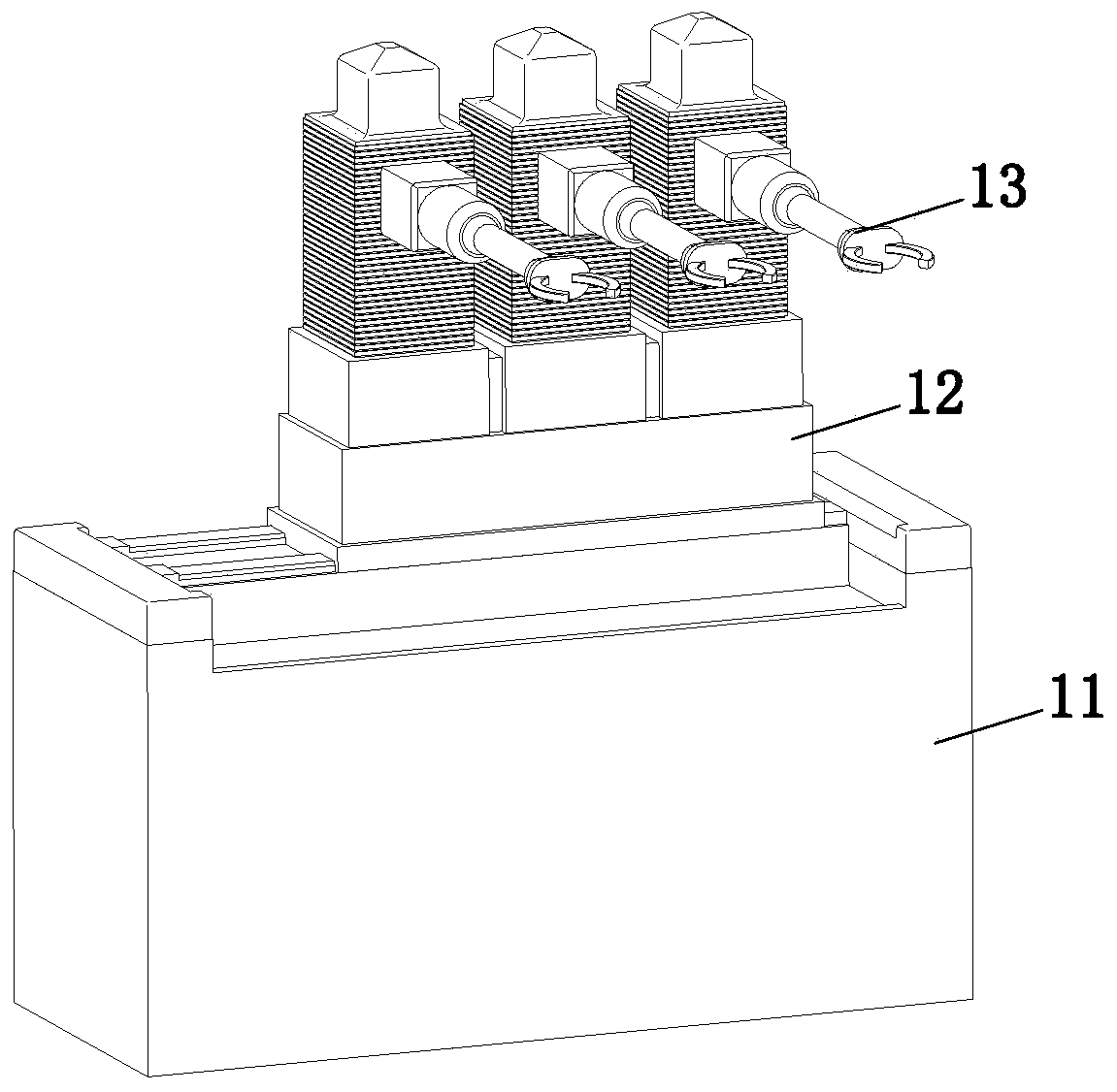
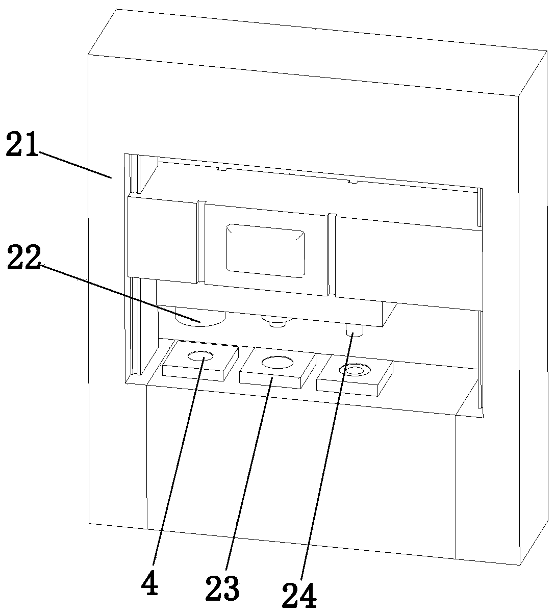
[0023] refer to Figure 1 to Figure 4 It can be seen that an automatic precision forging singles production line for bearings includes a material transfer mechanism 1, a processing mechanism 2 and a feeding conveyor belt 3, the material moving mechanism 1 is arranged on the side of the processing mechanism 2, and the feeding conveyor belt 3 is Set between the material transfer mechanism 1 and the processing mechanism 2, the processing mechanism 2 includes a high-tonnage punch press 21, an upsetting assembly 22, a punching assembly 23 and a bottom cutting assembly 24, the upsetting assembly 22, the ...


PUM


Abstract

The invention relates to the technical field of bearing machining, in particular to a bearing automatic finish forging single production line. The bearing automatic finish forging single production line comprises a material moving mechanism, a machining mechanism and a discharging conveying belt. The material moving mechanism is arranged beside the machining mechanism. The discharging conveying belt is arranged between the material moving mechanism and the machining mechanism. The machining mechanism comprises a high-tonnage punching machine, an upsetting assembly, a punching assembly and a bottom cutting assembly. The upsetting assembly, the punching assembly and the bottom cutting assembly are arranged below the high-tonnage punching machine at equal distance. A stepping beam works to drive three mechanical arms to work synchronously, three blanks are driven to move on the high-tonnage punching machine, single machining of bearing steel rings is achieved, the production line is short, temperature is uniform, product quality is improved, forging temperature is uniform, and production efficiency and forging precision are improved; and due to double mold motion of the punching assembly, the punching assembly can cooperate with the mechanical arms conveniently to discharge the blanks, manual discharging is not needed, automatic work can be achieved on production of the bearing steel rings conveniently, and production efficiency is improved.

Description

technical field [0001] The invention relates to the technical field of bearing processing, in particular to an automatic precision forging single production line for bearings. Background technique [0002] The production of bearing steel rings requires upsetting, forming, and bottom-cutting processes, and the three processes use multi-function high-tonnage punching machines. Sleeves are used in the prior art (the material that falls after cutting the bottom of the steel is processed, processed into the inner ring of the bearing, and a single production line produces the inner and outer ring of the bearing). [0003] However, there are still the following disadvantages when using the existing technology in production. First, multiple equipments are needed when using the way of sleeve punching to produce, and the long production line will easily lead to uneven temperature, and the sleeve punching product is easy to produce burrs , The material of the inner ring is loose, whic...

Claims


Application Information

Patent Timeline
Patent Type & Authority Applications(China)
IPC IPC(8): B21K1/04B21D53/10B21D28/34B21J9/06B21K27/00B21D37/18B21D45/02B21D43/10
CPCB21D28/34B21D37/18B21D43/105B21D45/003B21D45/02B21D53/10B21J9/06B21K1/04B21K27/00
Inventor 毛永成毛赛赛
Owner 浙江赛赛轴承有限公司
Why Eureka
Try Eureka