Clamping fixture for milling forks

A technology of fixing devices and jaws, which is applied in the direction of positioning devices, clamping, milling machine equipment, etc., can solve the problems of low working efficiency of milling forks, and achieve the effects of simple structure, improved processing efficiency and convenient operation

Active Publication Date: 2020-12-29
贵州友擘机械制造有限公司
View PDF7 Cites 0 Cited by
  • Summary
  • Abstract
  • Description
  • Claims
  • Application Information

AI Technical Summary

Problems solved by technology

[0003] The present invention intends to provide a clamping and fixing device for milling forks to solve the technical problem of low working efficiency of milling forks in the prior art

Method used


Image

  • Clamping fixture for milling forks
  • Clamping fixture for milling forks
  • Clamping fixture for milling forks

Examples


Embodiment 1

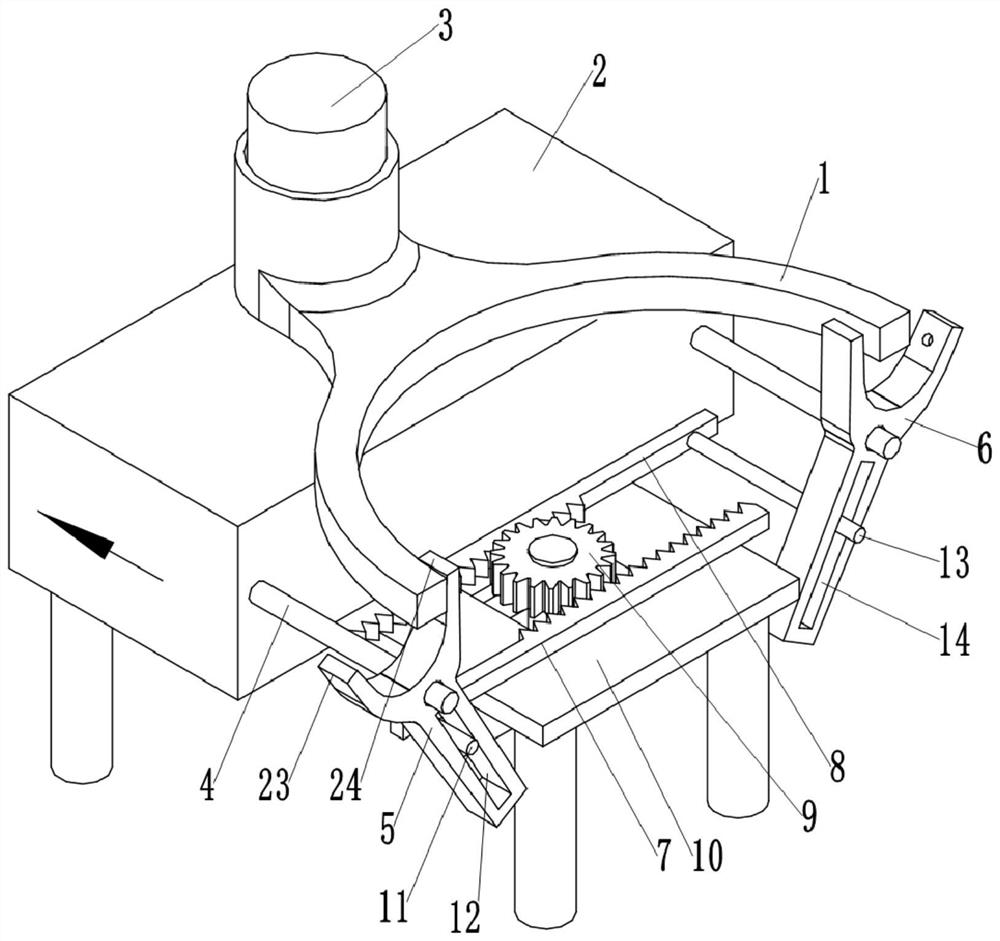
[0031] as attached figure 1 Shown: The clamping and fixing device for the milling fork, including the frame 2 and the fixing mechanism for clamping the shift fork 1, the fixing mechanism includes the positioning column 3, the first hinged swing rod 5 and the second hinged swing rod 6 , the positioning column 3 is fixed vertically on the upper surface of the frame 2, the first hinged swing link 5 and the second hinged swing link 6 are located on the same side of the positioning column 3, the first hinged swing link 5 and the second hinged swing link 6 With respect to the mirror-symmetrical setting of the positioning column 3, the setting method of the second hinged swing rod 6 is the same as that of the first hinged swing rod 5. Here, the setting method of the first hinged swing rod 5 is used as an example for illustration: the first hinged swing rod 5 The upper end is integrally formed with a left jaw 23 and a right jaw 24, the frame 2 is fixedly provided with a horizontal bar...

Embodiment 2

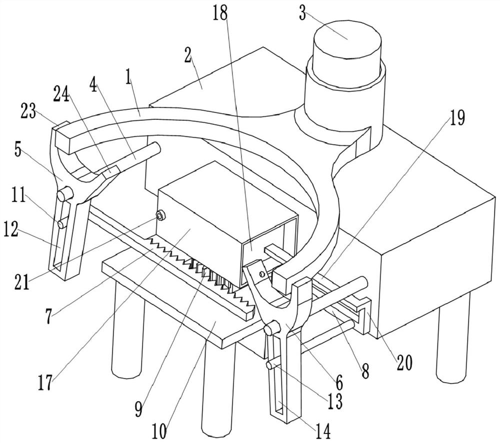
[0035] Such as image 3 As shown, the difference between the present embodiment and the first embodiment is that a sealing cylinder 17 is fixedly connected to the frame 2 by bolts, a piston 18 is slidably connected in the sealing cylinder 17, and a piston rod 19 is clamped and fixed on the right side of the piston 18. The piston 18 is provided with an air inlet, and the air inlet is provided with a one-way valve for allowing gas to flow into the sealed cylinder 17 only from the outside; the right end of the piston rod 19 is welded to the second rack 8 through an L-shaped connecting rod 20 Fixed; the sealing cylinder 17 is provided with an air outlet, and the air outlet is integrally formed with a connection port 21, and the connection port 21 is communicated with a first flexible pipe and a second flexible pipe (not shown in the figure) through a three-way pipe. Both the hinged swing rod 5 and the second hinged swing rod 6 are provided with an air flow passage 22, the first fl...


PUM


Abstract

The invention relates to the technical field of a clamping and fixing device and discloses a clamping and fixing device for a milling shifting fork. The device comprises a rack, wherein a positioningcolumn for pre-positioning a workpiece is fixedly arranged on the rack, a first hinge swing rod and a second hinge swing rod are further hinged to the rack, the first hinge swing rod and the second hinge swing rod are located on one side of the positioning column, the first hinge swing rod and the second hinge swing rod are arranged in a mirror symmetry mode relative to the positioning column, a left clamping jaw and a right clamping jaw are fixedly arranged on the first hinge swing rod, the left clamping jaw, the right clamping jaw and the first hinge swing rod are distributed in a Y shape, and a driving mechanism used for driving the first hinge swing rod and the second hinge swing rod to swing is further arranged on the rack. The device can solve a technical problem that in the prior art, working efficiency of shifting fork milling is low.

Description

technical field [0001] The invention relates to the technical field of clamping and fixing devices, in particular to a clamping and fixing device for a milling fork. Background technique [0002] The shift fork is a part of the car gearbox, mainly used for clutch shifting, so the quality of the shift fork is directly related to the safety factor of the car. In the prior art, when the shift fork is milled, the shift fork is generally fixed by a three-point fixing method, and then milled. However, the prior art tends to cause multiple positions of the shift fork to be blocked by the fixing clip, resulting in incomplete milling of the shift fork. Problems, which in turn lead to multiple positioning and fixing of the shift fork, resulting in longer milling time of a single shift fork, and low milling efficiency of the shift fork. Contents of the invention [0003] The present invention intends to provide a clamping and fixing device for a milling fork to solve the technical p...

Claims


Application Information

Patent Timeline
Patent Type & Authority Patents(China)
IPC IPC(8): B23C3/00B23Q3/06B23Q11/00
CPCB23C3/00B23Q3/062B23Q11/005
Inventor 陈明友
Owner 贵州友擘机械制造有限公司
Why Eureka
Try Eureka