Vertical machining tool

A processing machine tool and vertical technology, which is applied in the direction of metal processing machinery parts, metal processing equipment, manufacturing tools, etc., can solve the problems of spindle rotation and other problems, and achieve the effect of ensuring processing accuracy

Active Publication Date: 2020-04-21
枣庄北航机床创新研究院有限公司
View PDF13 Cites 1 Cited by
  • Summary
  • Abstract
  • Description
  • Claims
  • Application Information

AI Technical Summary

Problems solved by technology

[0003] The invention provides a vertical processing machine tool, which solves the problem in the prior art that the main shaft of the vertical processing machine tool rotates under the action of torque

Method used


Image

  • Vertical machining tool
  • Vertical machining tool
  • Vertical machining tool

Examples


Embodiment 1

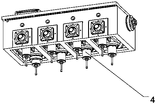
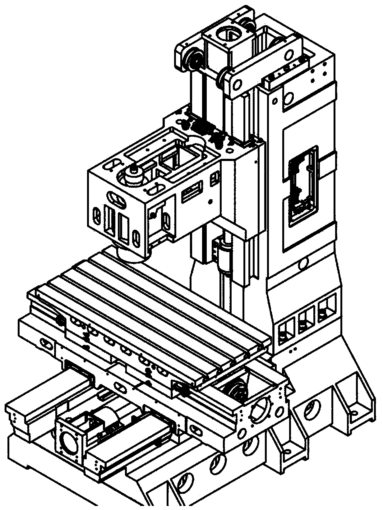
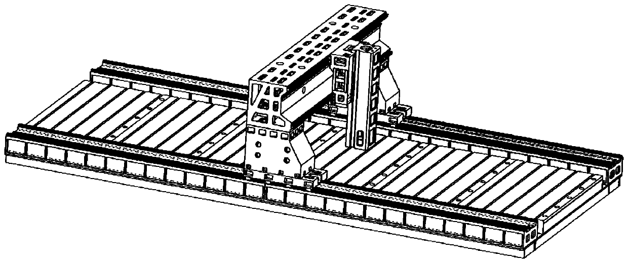
[0022] like Figure 3-5 As shown, a vertical processing machine tool includes a bed 5 and a Z-axis sliding table 1. Two columns 2 are fixedly connected to the bed. The Z-axis slide rail 3 is slidably connected, and the middle part of the Z-axis slide table 1 is provided with a main shaft 4 , and the main shaft 4 is located below the Z-axis slide table 1 . The column 2 is fixedly connected with the bed 5, the relative movement of the workpiece and the spindle 4 in the horizontal direction is realized by the relative movement of the worktable and the spindle 4, and the relative movement of the workpiece and the spindle 4 in the vertical direction is realized by the movement of the Z-axis slide table 1 Realize that when the Z-axis sliding table 1 moves, in addition to the vertical movement, there is also a horizontal movement, and the workbench needs to be moved accordingly to eliminate the influence of the Z-axis sliding table 1 movement. Since the main shaft 4 is located direc...

Embodiment 2

[0027] The difference between this embodiment and Embodiment 1 is that the angle between the Z-axis slide rail 3 and the horizontal plane is 30°, the Z-axis slide rail 3 is located on the top surface of the column 2, and the angle between the top surface of the column 2 and the horizontal plane is 30°. °. The Z-axis slide rail 3 is perpendicular to the Y-axis slide rail 8 . When the Z-axis slide table 1 moves along the Z-axis slide rail 3, the X-axis slide table 7 needs to move along the X-axis slide rail 9 to eliminate the influence.

Embodiment 3

[0029] The difference between this embodiment and Embodiment 1 is that the angle between the Z-axis slide rail 3 and the horizontal plane is 60°, the Z-axis slide rail 3 is located on the top surface of the column 2, and the angle between the top surface of the column 2 and the horizontal plane is 50°. °. At this time, there is a certain angle between the orthographic projection of the Z-axis slide rail 3 on the top surface of the bed 5 and the Y-axis slide rail 8 and the X-axis slide rail 9 . When the Z-axis slide 1 moves along the Z-axis slide 3, the X-axis slide 7 needs to move along the X-axis slide 9, and the Y-axis slide 6 moves along the Y-axis slide 8 to eliminate the movement of the Z-axis slide 1. Impact.


PUM


Abstract

The invention provides a vertical machining tool. The machine tool comprises a machine tool body and a Z-axis sliding table, two stand columns are fixedly connected to the machine tool bed. A Z-axis sliding rail is arranged on the stand columns. The two ends of the Z-axis sliding table are slidably connected with the Z-axis sliding rail. A main shaft is arranged in the middle of the Z-axis slidingtable; the main shaft is located below the Z-axis sliding table, a Y-axis sliding table is slidably connected to the machine tool bed through a Y-axis sliding rail, an X-axis sliding table is slidably connected to the Y-axis sliding table through an X-axis sliding rail, the Y-axis sliding rail and the X-axis sliding rail are horizontally arranged, the Y-axis sliding rail and the X-axis sliding rail are perpendicular to each other, and the included angle between the Z-axis sliding rail and the horizontal plane is 30-60 degrees. Through ingenious design of the vertical machining machine tool, the problem that in the prior art, a main shaft of a vertical machining machine tool rotates under the effect of torque is solved.

Description

technical field [0001] The invention relates to the field of processing machine tools, in particular to a vertical processing machine tool. Background technique [0002] Traditional vertical processing machine tools are generally single-column or gantry-type. The movement axis of the machine tool follows the principle of Cartesian coordinates. It has a simple structure and is easy to operate. However, due to its own structural form, the main shaft of this type of processing machine tool is a cantilever structure. The main shaft is the main working part of the processing bed, and it is usually heavy. like figure 1 In the single-column machine tool shown, the main shaft is located on the side of the column. Due to the installation accuracy and the strength of the workpiece, the main shaft will rotate under the action of the moment. Because of the special structure of the single-column, the main shaft is relatively There are certain cantilever features to ensure sufficient tr...

Claims


Application Information

Patent Timeline
Patent Type & Authority Applications(China)
IPC IPC(8): B23Q1/01B23Q1/26
CPCB23Q1/017B23Q1/26
Inventor 陈志同胡少南孙承明
Owner 枣庄北航机床创新研究院有限公司
Why Eureka
Try Eureka