Driving device for optical inspection outside material cabin and exposure platform

A driving device and installation platform technology, which is applied in the direction of analyzing materials, measuring devices, motor vehicles, etc., can solve the problems that the driving mechanism cannot adapt to the space environment, safety and reliability cannot be satisfied, and achieves strong adaptability to special space environments, Realize the effect of all-round monitoring and strong environmental adaptability

Active Publication Date: 2020-04-21
TECH & ENG CENT FOR SPACE UTILIZATION CHINESE ACAD OF SCI
View PDF5 Cites 4 Cited by
  • Summary
  • Abstract
  • Description
  • Claims
  • Application Information

AI Technical Summary

Problems solved by technology

[0025] The technical problem to be solved by the present invention is that there is currently no relevant drive mechanism for optical inspection of materials outside the cabin, and the general drive mechanism cannot adapt to the space environment, and the safety and reliability cannot meet the requirements of the special environment outside the space station experiment cabin.

Method used


Image

  • Driving device for optical inspection outside material cabin and exposure platform
  • Driving device for optical inspection outside material cabin and exposure platform
  • Driving device for optical inspection outside material cabin and exposure platform

Examples


Embodiment 1

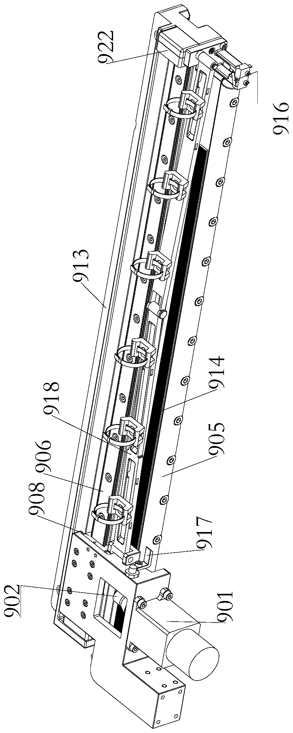
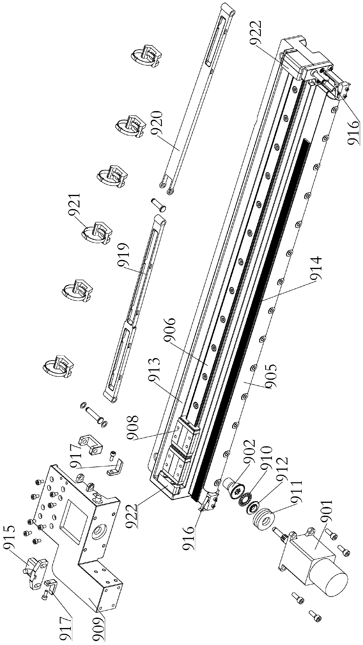
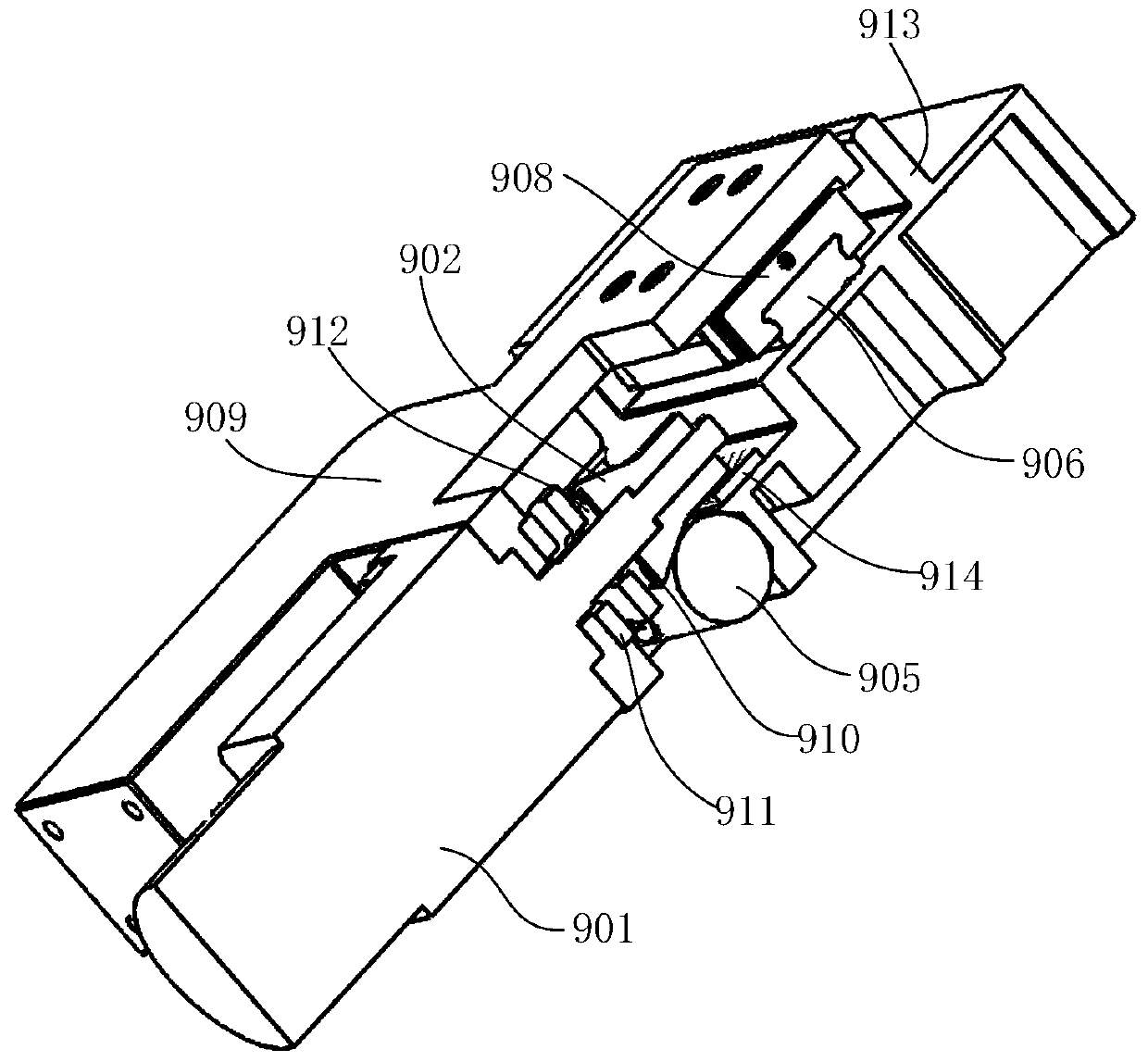
[0075] like Figure 1-Figure 11 As shown, a driving device for optical inspection of materials outside the cabin in this embodiment includes:

[0076] Driving mechanism two 901;

[0077] A conical friction wheel 902, the conical friction wheel 902 is spline-connected with the output shaft of the second driving mechanism 901;

[0078] A friction rod 905, the friction rod 905 is in friction fit with the conical friction wheel 902; the conical outer peripheral side of the conical friction wheel 902 abuts on the friction rod 905;

[0079] a guide rail 906, the guide rail 906 is arranged parallel to the friction bar 905;

[0080] A slider assembly 907, one end of the slider assembly 907 is slidably mounted on the guide rail 906, and the other end is fixedly connected to the casing of the second driving mechanism 901;

[0081] A load spring 910, the load spring 910 is sheathed on the output shaft of the drive mechanism 2 901, and sandwiched between the big end of the conical fric...

Embodiment 2

[0134] A material exposed platform outside the cabin of this embodiment, such as Figure 1-Figure 11 As shown, it includes a test box, an optical inspection module, an installation platform 800 and the driving device described in Embodiment 1, the test box is installed on the installation platform 800, and the exposed surface of the test box after opening faces the installation The surroundings of the platform 800 are arranged, and the guide rails are located near the peripheral side of the installation platform 800; the bottom of the support 701 is provided with a connecting plate 714 vertically arranged therewith, and the connecting plate 714 is connected to the second driving mechanism. , the optical inspection module 1 reciprocates in a direction perpendicular to the installation platform 800 under the drive of the steel wire rope 705, and reciprocates around the circumference of the installation platform 800 under the drive of the driving mechanism 2 , to inspect the expo...


PUM


Abstract

The invention relates to a driving device for optical inspection outside a material cabin and an exposure platform. The driving device comprises a driving mechanism II, and a conical friction wheel isin splined connection with the output shaft of the driving mechanism II; a friction rod is in friction fit with the conical friction wheel; the conical peripheral side of the conical friction wheel abuts against the friction rod; a guide rail is parallel to the friction rod; a load spring sleeves the output shaft of the driving mechanism II and is clamped between the large head end of the conicalfriction wheel and the other end of a sliding block assembly; the bottom of ta support is installed on the driving mechanism II, a first guide rail perpendicular to the guide rail is installed on oneside of the support, a driving mechanism is installed at the bottom of one side of the support, the driving end of the driving mechanism is connected with a driving steel wire rope winding wheel, a steel wire rope idler is installed at the top of one side of the support, and a steel wire rope tightening device is installed on the other side of the support. The driving requirement of an optical inspection module under the special space environment effect can be met.

Description

technical field [0001] The invention relates to the field of exposure of aerospace materials, in particular to a driving device and an exposure platform for optical inspection of materials outside the cabin. Background technique [0002] In space science research, it is inseparable from the use of various materials, especially new materials. The purpose of material space environment exposure experiment is to study the service behavior of materials under the effect of special space environment. [0003] Therefore, in the material cabin exposure experiment, how to realize a material cabin that can provide conditions for the on-orbit exposure of materials, provide conditions for the on-orbit movement of the optical imaging inspection module, and realize on-orbit detection in a special and complex space The external exposure platform is an important problem that needs to be solved urgently. [0004] Moreover, the movement mechanism applied to the space environment, compared wi...

Claims


Application Information

Patent Timeline
Patent Type & Authority Applications(China)
IPC IPC(8): B64G1/10B64G1/66G01N17/00
CPCB64G1/105B64G1/66G01N17/00G01N17/002G01N17/004
Inventor 张聚乐张伟贵王乐天王珂冯振华王辅辅乔志宏
Owner TECH & ENG CENT FOR SPACE UTILIZATION CHINESE ACAD OF SCI
Why Eureka
Try Eureka