Conveying device used for steel product production

A conveying device and steel technology, applied in the field of conveying belts, can solve the problems of irregular shape of steel, scratching of guard plates, accumulation of steel and jamming conveying belts, etc., and achieve the effect of ensuring conveying efficiency, ensuring equipment operation and prolonging the service life of equipment.

Active Publication Date: 2020-04-21
HUAINAN UNITED UNIVERSITY
View PDF5 Cites 2 Cited by
  • Summary
  • Abstract
  • Description
  • Claims
  • Application Information

AI Technical Summary

Problems solved by technology

[0004] The object of the present invention is to provide a conveying device for steel production to solve the problem of the existing conveying device for steel production proposed in the above-mentioned background technology, which has irregular shapes of steel and often has a certain height between two adjacent processes Poor, when the traditional conveyor belt transports steel, the steel tends to slide with the belt body of the conveyor belt, and scratches with the guard plates on both sides, and even causes the problem that the steel piles up and gets stuck on the conveyor belt

Method used


Image

  • Conveying device used for steel product production
  • Conveying device used for steel product production
  • Conveying device used for steel product production

Examples


Embodiment

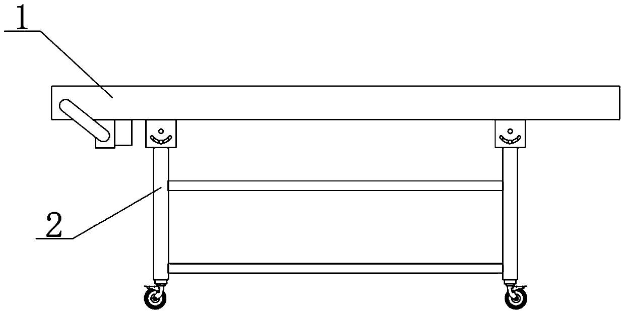
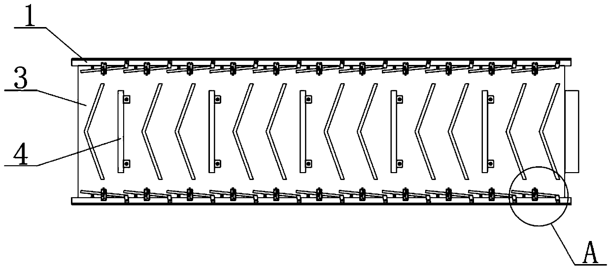
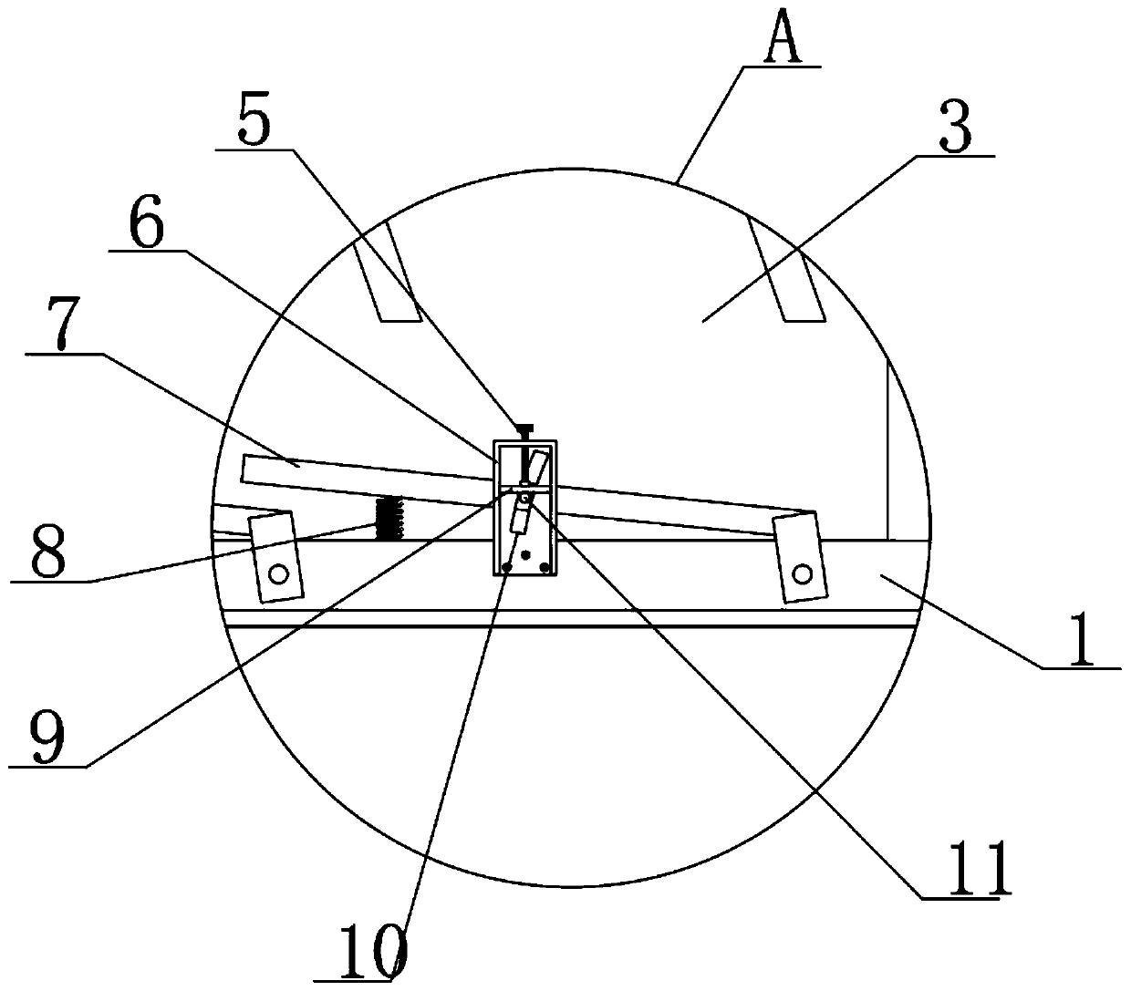
[0023] See Figure 1-Figure 5 , The present invention provides a technical solution: a conveying device for steel production, comprising a side plate 1, a support column 2, a conveyor belt body 3 and a connecting plate 13. The side plates 1 are symmetrically distributed on both sides of the conveyor belt body 3. , The lower end of the support column 2 is equipped with a universal wheel, the upper surface of the side plate 1 is installed with a baffle 7 through the connecting block and the rotating shaft, the lower end of the baffle 7 is in clearance fit with the upper surface of the conveyor belt 3, the baffle 7 A return spring 8 is fixedly connected between the free end of the member and the inner surface of the side plate 1, the upper surface of the baffle 7 is welded and fixed with a fixing rod 11, and the upper surface of the side plate 1 is fixed with a sliding box 6 by screws. The inner bottom surface of 6 is provided with a sliding groove 10, the upper end of the fixed r...


PUM


Abstract

The invention discloses a conveying device used for steel product production. The conveying device comprises side plates, supporting columns, a transporting belt body and a connecting plate. The sideplates are symmetrically distributed on the two sides of the transporting belt body. Universal wheels are mounted at the lower ends of the supporting columns correspondingly. Baffles are mounted rotationally on the upper surfaces of the side plates through connecting blocks and rotary shafts correspondingly. The lower ends of the baffles are in clearance fit with the upper surface of the transporting belt body. Reset springs are fixedly connected between component free ends of the baffles and the inner side surfaces of the side plates correspondingly. Fixing rods are fixedly arranged on the upper surfaces of the baffles correspondingly. Sliding boxes are fixedly arranged on the upper surfaces of the side plates correspondingly. By designing the baffles, the side plates are protected against damage; meanwhile, by means of the retractility of the reset springs, the resistance of a transporting belt is prevented from being increased suddenly, and the transporting belt is protected againstdamage; and in addition, the maximum included angle between the baffles and the side plates can be regulated and controlled by rotating first lead screws, the steel product conveying efficiency is guaranteed, the protection effect of the device is better than that of a traditional conveying device, and the equipment service life is prolonged.

Description

Technical field [0001] The invention belongs to the technical field of conveyor belts, and specifically relates to a conveyor device for steel production. Background technique [0002] In the production and processing process of steel, it needs to go through multiple production and processing processes such as blanking, sending and forming. The transfer and transportation of steel products between two adjacent processes is generally achieved through conveyor belts. [0003] The existing conveying device for steel production has regular and irregular steel shapes, and there is often a certain height difference between two adjacent processes. When the traditional conveyor belt conveys steel, the steel is easy to slide with the belt body of the conveyor belt. And it scratches with the guard plates on both sides, and even causes the problem of steel accumulation and jamming the conveyor belt. For this reason, we propose a conveyor device for steel production. Summary of the invention ...

Claims


Application Information

Patent Timeline
Patent Type & Authority Applications(China)
IPC IPC(8): B65G15/58B65G21/20B65G21/00B65G41/00B65G45/18
CPCB65G15/58B65G21/00B65G21/2045B65G41/008B65G45/18B65G2812/02217
Inventor 牛国鹏沈相应尹建设
Owner HUAINAN UNITED UNIVERSITY
Why Eureka
Try Eureka