
Material splitting device and material splitting method

A diversion device and material technology, applied in the direction of transportation and packaging, conveyor objects, etc., can solve the problems of high labor intensity, increased labor costs, and easy fatigue of operations, etc., to achieve strong practicability, multiple applicable scenarios, and simple device structure Effect

Pending Publication Date: 2020-04-21
富联精密电子(郑州)有限公司
View PDF0 Cites 0 Cited by
  • Summary
  • Abstract
  • Description
  • Claims
  • Application Information

AI Technical Summary

Problems solved by technology

However, this method leads to increased labor costs, and the labor intensity of the personnel is high, and the work is prone to fatigue

Method used


Image

  • Material splitting device and material splitting method
  • Material splitting device and material splitting method
  • Material splitting device and material splitting method

Examples


Embodiment Construction

[0046] The drawings illustrate embodiments of the invention, which may be embodied in many different forms and should not be construed as limited to only the embodiments set forth herein. Rather, these embodiments are provided so that the disclosure of the present invention will be more thorough and complete, and the scope of the present invention will be fully understood by those skilled in the art. In the drawings, the dimensions of layers and regions are exaggerated for clarity.

[0047] Unless otherwise defined, all terms (including technical and scientific terms) used herein have the same meaning as commonly understood by one of ordinary skill in the art to which this invention belongs. It should also be understood that terms, such as those defined in commonly used dictionaries, should be interpreted to have a meaning consistent with their meaning in the context of the relevant field, and not to be interpreted in an overly idealistic or overly formal sense , unless expli...


PUM


Abstract

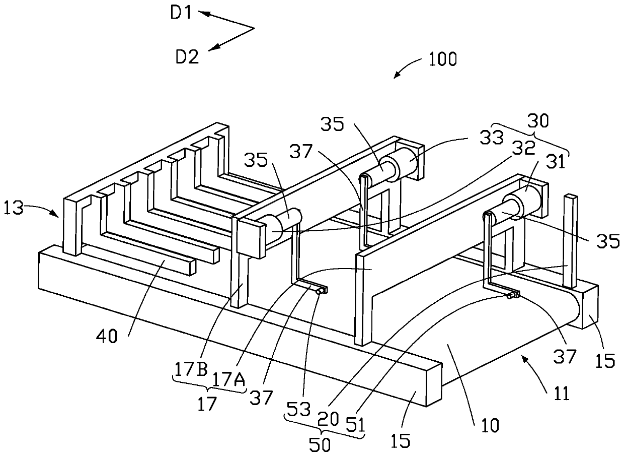
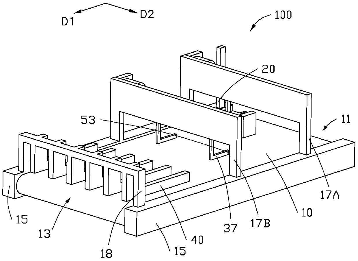
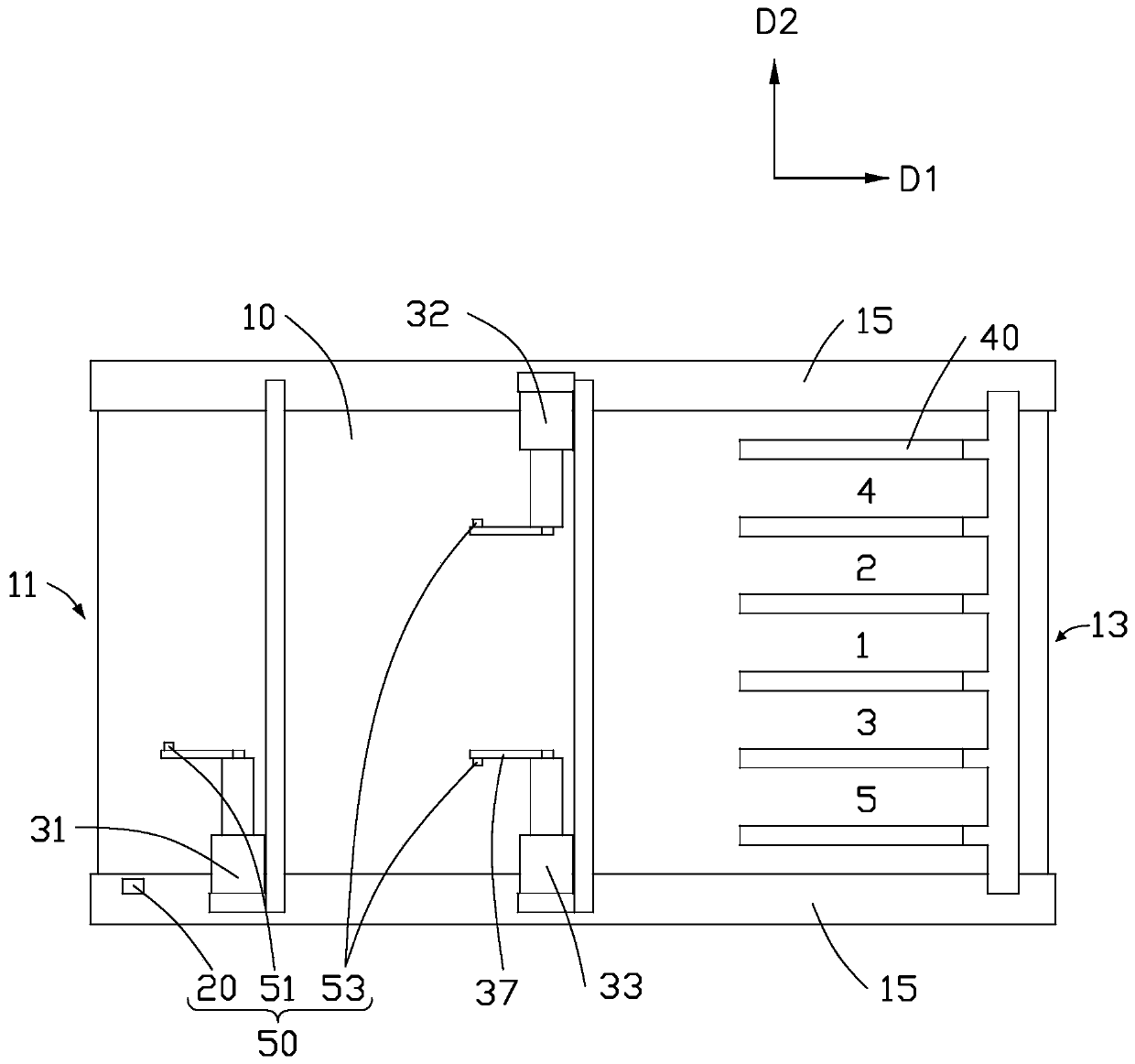
The inventio relates to a material splitting device. The material splitting device comprises a conveying part, a material sensor and an air cylinder; the material sensor is used for sensing a materialpassing through the conveying piece; and the air cylinder is arranged above the conveying piece, coupled with the material sensor and used for pushing the material on the conveying piece according toa material passage sensing result sensed by the material sensor, so that a plurality of splitting channels for splitting the material are formed on the conveying piece. The invention further providesa material splitting method. The material splitting device can be used for quickly splitting a large quantity of materials which are outputted and cannot be treated in time by the next station and sending the split materials to a plurality of work stations. The device has the advantages of simple structure, multiple application scenes and high practicability.

Description

technical field [0001] The invention relates to a material splitting device and a material splitting method. Background technique [0002] The existing assembly line belt usually transports materials along one direction, and the materials are usually arranged one after the other on the belt in a single row. If the assembly line belt outputs a lot of materials, and the next station of the assembly line belt cannot process more materials in time, material accumulation and omission will occur. An existing solution is to lengthen the assembly line and increase manpower to be located on both sides of the assembly line belt. However, this method leads to increased labor costs, and the labor intensity of the personnel is high, and the operation is prone to fatigue. Contents of the invention [0003] In view of this, it is necessary to provide a material distribution device that can effectively solve the above problems. [0004] A material distribution device comprising: [00...

Claims


Application Information

Patent Timeline
IPC IPC(8): B65G47/49B65G47/82
CPCB65G47/49B65G47/82
Inventor 贺文诚徐旭辉华长远崔家兴李闯
Owner 富联精密电子(郑州)有限公司
Learn More