Electric power anti-wind anti-overturning inner expansion electric pole foundation

A technology of pole foundation and internal expansion, applied in infrastructure engineering, building types, buildings, etc., can solve problems such as damage, waste of investment, and difficulty in implementation, and achieve the effect of avoiding land acquisition problems and improving pull-out resistance.

Inactive Publication Date: 2020-04-21
张若玮
View PDF5 Cites 0 Cited by
  • Summary
  • Abstract
  • Description
  • Claims
  • Application Information

AI Technical Summary

Problems solved by technology

When the traditional power grid pole foundation does not meet the windproof requirements, the windproof reinforcement measures adopted have different degrees of advantages and disadvantages. For example, the installation of windproof pull wire measures has a better effect on the overall reinforcement of the pole, but it needs to occupy a large area of ​​the ground. Land acquisition Difficult, some on-site conditions make it difficult to implement and affect the appearance; if the sleeve foundation of the pole is added, the overturning resistance of the foundation is better, but it is necessary to pull out the pole and bury the sleeve foundation and then re-lift the pole, which requires a power outage. Moreover, the sleeve foundation lacks an adjustment mechanism, which makes it difficult to correct the poles; if the cast-in-place concrete foundation for the poles is added, the foundation and the poles will be integrated after construction. When the poles are replaced or the lines are moved later, the foundation cannot be reused. waste of investment
In addition, there are many types of poles in the distribution network because the foundation does not meet the windproof requirements, and the problem of land acquisition often becomes a difficult problem that restricts the windproof reinforcement of the poles, so there is always the risk of serious damage after the typhoon comes.

Method used


Image

  • Electric power anti-wind anti-overturning inner expansion electric pole foundation
  • Electric power anti-wind anti-overturning inner expansion electric pole foundation

Examples


Embodiment Construction

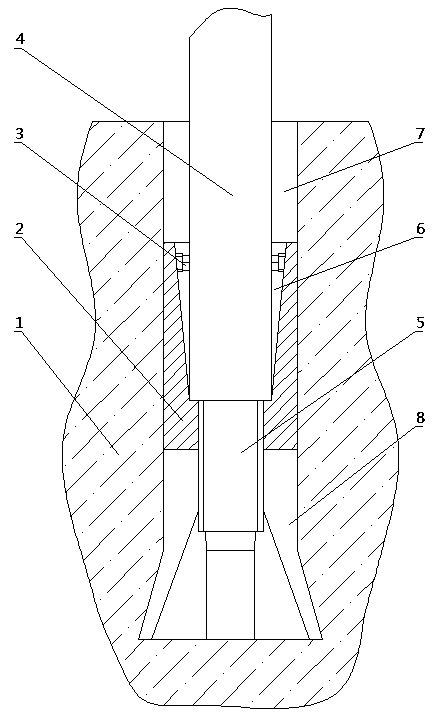
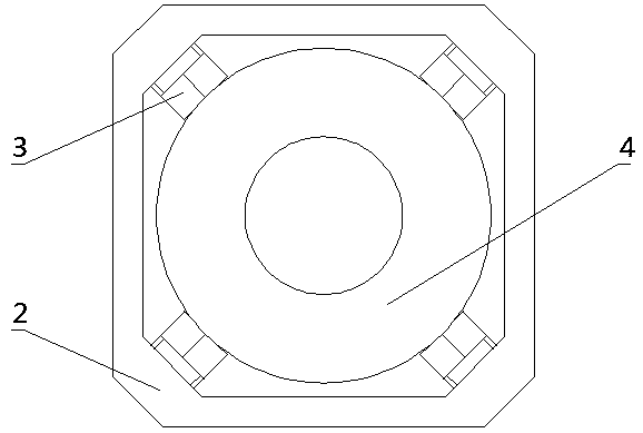
[0023] As shown in the figure, the foundation 2 is placed on the ground 1. After straightening, it can be directly driven or pressed into the ground with a beating or pressing machine. For large lengths, it is set up in sections and connected to each other during on-site operations. , to eliminate the difficulty of transportation and suppression. This foundation 2 bottoms or establishes four direction expansion plates 8, concrete quantity can increase or decrease according to the situation, each direction expansion plate 8 they are combined and internally establishes tapered screw holes, and screw rod 5 is screwed in the tapered screw holes; After pressing into the ground, tighten the screw rod 5 so that the lower part of the expansion plate is claw-shaped to strengthen the opening in all directions, and the lower part is claw-shaped to strengthen the stability and pull-out resistance of the foundation 2; the shape of the foundation 2 or It is rectangular and can automatically...


PUM


Abstract

The invention provides an electric power anti-wind anti-overturning inner expansion electric pole foundation which is arranged below the ground and is used for supporting an electric pole, so that theelectric pole has better wind resistance, overturning resistance and pulling resistance; when the electric pole is replaced or a line is migrated in the future, the foundation can be reused, and investment is not wasted. The electric power anti-wind anti-overturning inner expansion electric pole foundation is characterized in that the foundation is placed on the ground, and is directly driven orpressed into the ground after being straightened; the lower part of the foundation may be provided with four expansion plates, the expansion plates can be separately expanded in all directions by screwing a screw rod, and the lower part is claw-shaped so as to enhance the stability and the pulling resistance of the foundation; and the upper part of the foundation is provided with an inverted horn-shaped counter bore, positioning bolts are arranged around the upper part of the inverted horn-shaped counter bore, a heavy-duty electric power pole is placed in the inverted horn-shaped counter bore,the lower end of the heavy-duty electric power pole is clamped at the bottom of the inverted horn-shaped counter bore, the vertical degree of the heavy-duty electric power pole is firstly adjusted bythe positioning bolts, then a wedge block is inserted into the inverted horn-shaped counter bore to further fix the heavy-duty electric power pole, and finally a hole pit is filled with soil.

Description

technical field [0001] The invention relates to an electric pole foundation. Background technique [0002] The pole tower is the general term for the pole and the iron tower. It is vertically arranged on the ground as a support device for the overhead line. Keep a certain safe distance between objects; the underground devices of the tower are collectively called the foundation, and the foundation is used to stabilize the tower so that the tower will not be pulled up, sinking or toppled due to vertical load, horizontal load, accidental disconnection tension and external force. [0003] The excavation of the traditional power grid pole foundation usually requires two people to use a "shovel and scoop" to excavate a foundation pit with a depth of about 2 meters. It takes 4 hours to complete, which is inefficient and consumes too much physical strength of the workers. Large, in the case of water accumulation in the foundation pit, use the water and mud scooped out when digging ...

Claims


Application Information

Patent Timeline
IPC IPC(8): E02D27/42E02D35/00E04H12/22
CPCE02D27/42E02D35/00E04H12/2215E04H12/223
Inventor 张若玮
Owner 张若玮
Why Eureka
Try Eureka