Flying bar fixing seat and cavity filter

A fixed seat and flying rod technology, applied in the field of communication, can solve problems such as poor index, difficult installation, failure, etc., to prevent the processing tolerance from being too small, reduce shaking, and ensure stable combination.

Pending Publication Date: 2020-04-21
DONGGUAN ACE TECH
View PDF0 Cites 1 Cited by
  • Summary
  • Abstract
  • Description
  • Claims
  • Application Information

AI Technical Summary

Problems solved by technology

However, the way that the above-mentioned flying rod fixing seat is interference-fitted with the installation rib through the chute 93, when the width of the chute is too small, the installation will be difficult or even fail, and when the width of the chute is too large, it will cause shaking after installation. Moreover, there is no extrusion deformation in the vertical and horizontal directions of the flying rod fixing seat. When the tolerance of the flying rod fixing seat is larger than that of the installation position, it will also lead to installation difficulties or even failure. When the tolerance is small, Shaking phenomenon will also occur, resulting in poor indicators or even failure

Method used


Image

  • Flying bar fixing seat and cavity filter
  • Flying bar fixing seat and cavity filter
  • Flying bar fixing seat and cavity filter

Examples


Embodiment Construction

[0021] In order to describe the content, structural features, achieved goals and effects of the present invention in detail, the following will be described in detail in combination with the embodiments and accompanying drawings.

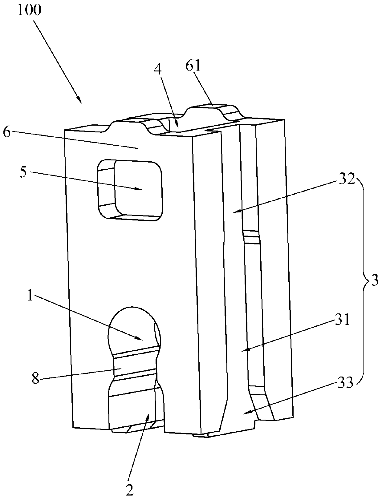
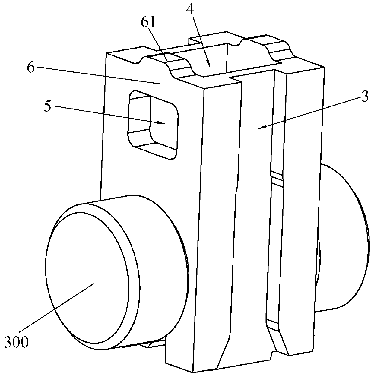
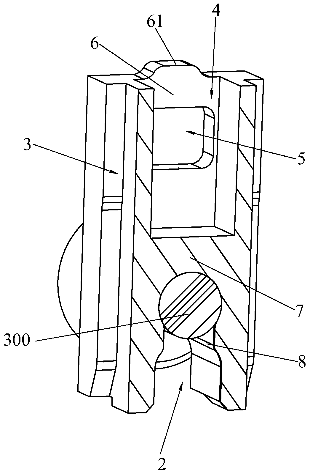
[0022] see Figure 1 to Figure 4 , the present invention discloses a flying rod holder 100. The flying rod holder 100 is in the shape of a cuboid as a whole. The lower part of the flying rod holder 100 is formed with a flying rod positioning hole 1 and a lower end opening 2 that penetrate front and rear. The upper end of the lower opening 2 It communicates with the fly rod positioning hole 1, the lower end of the lower opening 2 penetrates downward, the left and right sides of the fly rod holder 100 are respectively provided with vertically penetrating installation slots 3, and the upper part of the fly rod holder 100 is provided with a vertically extending And the groove 4 that penetrates upwards, the cross section of the groove 4 is rectangular, t...


PUM


Abstract

The invention discloses a flying bar fixing seat. The flying bar fixing seat is integrally cuboid. A flying rod positioning hole penetrating the front and back of the flying bar fixing seat and a lower end opening are formed in the lower part of the flying bar fixing seat; the upper end of the lower end opening is communicated with the flying bar positioning hole; the lower end of the lower end opening penetrates downwards; vertically-through mounting clamping grooves are formed in the left side and the right side of the flying bar fixing seat respectively; a groove which extends vertically and penetrates upwards the e flying bar fixing seat is formed in the upper part of the flying bar fixing seat; the section of the groove is rectangular; open grooves penetrating outwards through the flying bar fixing seat are formed in the front side wall and the rear side wall of the groove respectively; the left side and the right side of the groove are close to the two mounting clamping grooves respectively; two elastic beams are formed on the upper sides of the two open grooves of the flying bar fixing seat respectively; and protrusions protrude upwards are arranged in the middles of the elastic beams. With the flying bar fixing seat adopted, the phenomena of difficult installation or even unavailable installation and shaking after installation can be effectively reduced.

Description

technical field [0001] The invention relates to the field of communication technology, in particular to a flying rod fixing seat and a cavity filter. Background technique [0002] see Figure 5 , which provides a flying rod holder, the lower end of the flying rod holder is formed with a vertically penetrating flying rod positioning hole 91 and a lower end opening 92, the upper end of the lower end opening 92 communicates with the flying rod positioning hole 91, and the lower end opening 92 The lower end penetrates downward, the width of the lower end opening 92 is smaller than the width of the widest part of the fly rod positioning hole 91, and the two lateral side walls of the fly rod holder are formed with two vertically penetrating chutes 93, the chute 93 and the inside of the filter The mounting rib (not shown) is an interference fit. However, the way that the above-mentioned flying rod fixing seat is interference-fitted with the installation rib through the chute 93, w...

Claims


Application Information

Patent Timeline
Patent Type & Authority Applications(China)
IPC IPC(8): H01P1/207
CPCH01P1/207
Inventor 李承宪
Owner DONGGUAN ACE TECH
Why Eureka
Try Eureka