Flexible pipe filling end sealing machine

A tail sealing machine and hose technology, applied in packaging machines, packaging sealing/fastening, packaging, etc., can solve the problems of affecting production efficiency, poor continuity, limiting the reciprocating speed of connecting blocks, etc., and achieve fast forward and reverse switching, The effect of fast response and high production efficiency

Active Publication Date: 2020-04-24
烟台开发区创佳制药机械有限公司
View PDF5 Cites 6 Cited by
  • Summary
  • Abstract
  • Description
  • Claims
  • Application Information

AI Technical Summary

Problems solved by technology

[0004] In the current tail sealing machine, the tail sealing device is generally driven by a cylinder or a hydraulic cylinder as a power mechanism. The cylinder controls the reciprocating movement of the connecting block through continuous air intake and exhaust, and the expansion and contraction of the extension shaft of the cylinder is continuously controlled by the valve. Opening and closing realizes the execution of actions, that is, every time the cylinder is restarted, it takes a certain amount of time to start each time. The actions of the cylinder are intermittent and the continuity is poor, which will limit the connection of the block. Reciprocating speed, which affects production efficiency

Method used


Image

  • Flexible pipe filling end sealing machine
  • Flexible pipe filling end sealing machine
  • Flexible pipe filling end sealing machine

Examples


Embodiment

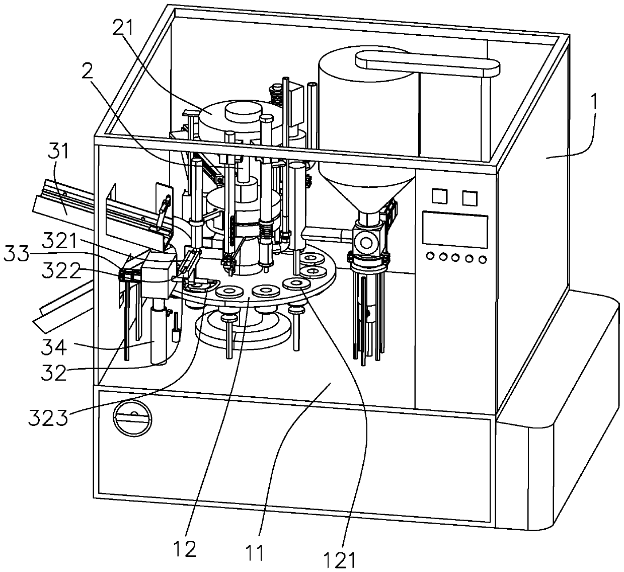
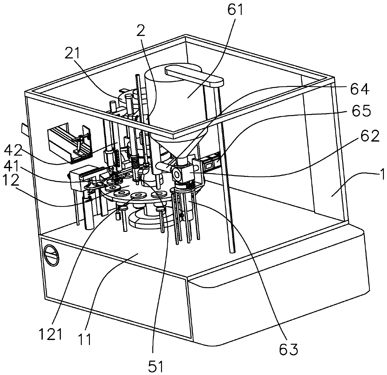
[0037] A high-speed hose filling and sealing machine, such as figure 1As shown, a frame 1 is included, and the frame 1 is provided with an upper pipe mechanism, a positioning mechanism, a dust removal mechanism, a filling mechanism, a heating mechanism, a clamping mechanism and an ejection mechanism. The frame 1 includes a workbench 11 on which a turntable 12 is rotatably connected. The turntable 12 is provided with a plurality of tube cups 121 in the circumferential direction, an upper pipe mechanism, a positioning mechanism, a dust removal mechanism, a filling mechanism, a heating mechanism, a clamping mechanism and a The outlet mechanism is arranged in sequence in the circumferential direction and corresponds to the tube cup 121. The tube cup 121 transports the hose, and the hose is sequentially processed through various processes until it is discharged.

[0038] Such as figure 1 As shown, the center of the turntable 12 is provided with a through hole and is vertically sli...


PUM


Abstract

The invention relates to the technical field of end sealing machines, and discloses a flexible pipe filling end sealing machine. The flexible pipe filling end sealing machine comprises a rack, whereinthe rack comprises a workbench; the workbench is provided with a rotary disk and a clamping mechanism; a sliding rail is in sliding connection with a first clamping claw and a second clamping claw; the first clamping claw is set into an n shape and comprises a control end and a clamping end; the second clamping claw just faces the clamping end; the upper end of a driving connecting rod is positioned between the control end and the second clamping claw; a control lever is rotatably connected in the sliding rail; the upper end of the driving connecting rod is hinged to the control lever througha bulb universal joint; and two ends of the control lever are independently abutted against the control end and the second clamping claw. Through the arrangement of a driving motor, the movement of the first clamping claw and the movement of the second clamping claw are both controlled through the driving motor, a response speed of the motor is high, positive and negative rotation can be quicklyswitched so as to control the first clamping claw and the second clamping claw to be quickly opened and closed, a flexible pipe is subjected to clamping and end sealing, and production efficiency is high.

Description

technical field [0001] The invention relates to the technical field of tail sealing machines, in particular to a hose filling and sealing machine. Background technique [0002] In the pharmaceutical, daily chemical, cosmetic and other production industries, it is necessary to smoothly and accurately inject various paste, paste, viscous fluids and other materials into the hose for packaging. The filling and sealing machine is a kind of equipment that injects various paste, paste, viscous fluids and other materials into the hose smoothly and accurately, and completes the sealing of the hose. [0003] The Chinese patent with publication number CN109592098A discloses a fully automatic hose filling and sealing machine, which includes a frame, a turntable arranged on the frame and a drive mechanism for driving the turntable to rotate on the frame, and also includes sequentially The feeding device, tube loading device, tube pressing device, filling device, clamping heat sealing de...

Claims


Application Information

Patent Timeline
Patent Type & Authority Applications(China)
IPC IPC(8): B65B65/00B65B3/12B65B55/24B65B51/14B65B51/10B65B43/50
CPCB65B3/12B65B43/50B65B51/10B65B51/14B65B55/24B65B65/003
Inventor 朱宏岩
Owner 烟台开发区创佳制药机械有限公司
Why Eureka
Try Eureka