Two-degree-of-freedom parallel-connection rotating platform with eccentric torque unloading device

An unloading device and eccentric torque technology, applied in the field of robots, can solve the problems of complex structure of the attitude adjustment platform, and achieve the effects of easy control, improved bearing capacity, and reduced eccentric load

Active Publication Date: 2020-04-24
YANSHAN UNIV
View PDF36 Cites 4 Cited by
  • Summary
  • Abstract
  • Description
  • Claims
  • Application Information

AI Technical Summary

Problems solved by technology

On the basis of the traditional parallel platform, the attitude adjustment platform is equipped with an unloading device with a steel wire r...

Method used


Image

  • Two-degree-of-freedom parallel-connection rotating platform with eccentric torque unloading device
  • Two-degree-of-freedom parallel-connection rotating platform with eccentric torque unloading device
  • Two-degree-of-freedom parallel-connection rotating platform with eccentric torque unloading device

Examples


Embodiment 1

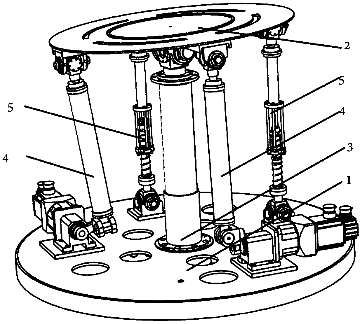
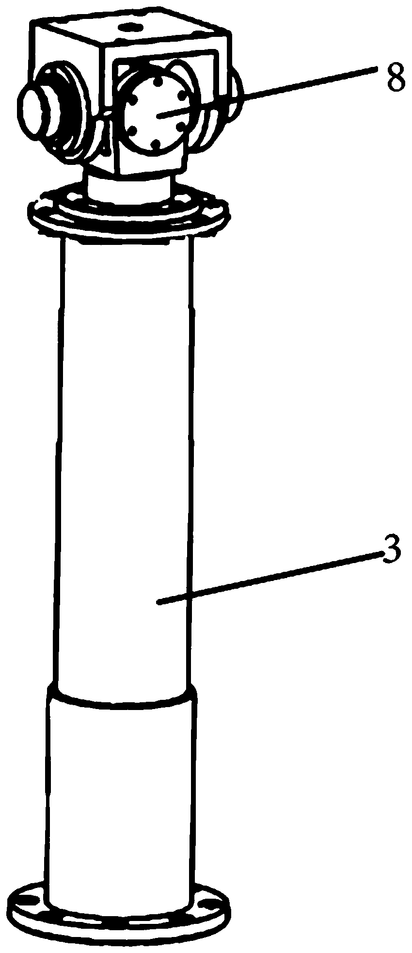
[0035] Such as Figure 1-8 As shown, a two-degree-of-freedom parallel rotating platform with an eccentric moment unloading device includes a fixed platform 1, a moving platform 2 is arranged above the fixed platform 1, and a supporting branch chain 3 is fixedly installed in the center of the fixed platform 1 , the top of the supporting branch chain 3 is hinged to the center of the moving platform 2; the fixed platform 1 has two driving branch chains 4 and two auxiliary branch chains 5 evenly around the axis of the supporting branch chain 3, and Two described drive branch chains 4 are adjacently arranged; The drive branch chains 4 are used to drive the outer edge of the moving platform 2 to move up and down; the bottom ends of the drive branch chains 4 are hinged with the fixed platform 1, so The top of the drive branch chain 4 is hinged with the moving platform 2;

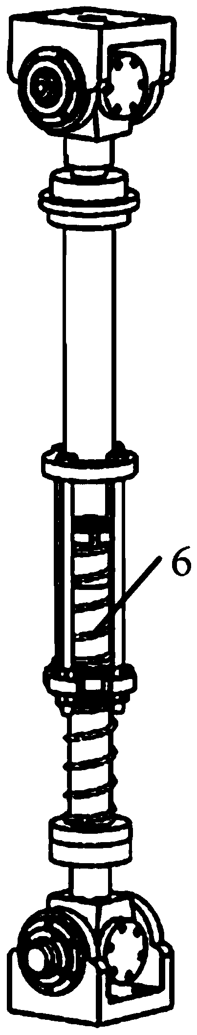
[0036] The auxiliary branch chain 5 includes a tension-compression spring device 6, and the tension-compression...

Embodiment 2

[0042] Such as Figure 2-5 with Figures 9 to 11 As shown, a two-degree-of-freedom parallel rotating platform with an eccentric moment unloading device. The difference between this embodiment and Embodiment 1 is that the driving branch chain 4 ′ includes an electric cylinder 407, the output end of the electric cylinder 407 is set upward, and the output end of the electric cylinder 407 is connected to the moving platform 2 is hinged, and the fixed end of the electric cylinder 407 is hinged with the fixed platform 1.

[0043] The fixed end of the electric cylinder 407 is hinged to the upper surface of the fixed platform 1 through the Hooke hinge II10, and the Hooke hinge II10 includes the first branch of the Hooke hinge fixedly connected to the bottom of the fixed end of the electric cylinder 407 Seat II1001, the second Hooke hinge support II1002 is provided under the first Hooke hinge support II1001, and the second Hooke hinge support II1002 is U-shaped, and the second Hooke ...


PUM


Abstract

The invention discloses a two-degree-of-freedom parallel-connection rotating platform with an eccentric torque unloading device. The platform comprises a fixed platform, a movable platform, a supporting branch chain, a driving branch chain and an auxiliary branch chain, wherein the auxiliary branch chain comprises a tension-compression spring device, the tension-compression spring device comprisesa lower supporting rod, the bottom end of the lower supporting rod is hinged to the fixed platform, the lower supporting rod is sleeved with an annular sleeve movably connected with the lower supporting rod, a radial locking nut is fixed to the top of the lower supporting rod, an upper compressed spring is installed between the radial locking nut and the annular sleeve, a lower compressed springis arranged between the annular sleeve and the bottom of the lower supporting rod, the outer wall of the annular sleeve is fixedly connected with the bottom of an upper supporting rod arranged above the lower supporting rod through a plurality of connecting columns, and the top of the upper supporting rod is hinged to the movable platform. According to the platform, on the basis of a traditional rotating platform, the auxiliary branch chain is additionally arranged, eccentric loads can be effectively reduced through tension-compression spring device of the auxiliary branch chain, and the bearing capacity of the rotating platform is greatly improved.

Description

technical field [0001] The invention relates to the field of robots, in particular to a two-degree-of-freedom parallel rotating platform with an eccentric moment unloading device. Background technique [0002] At present, due to its strong bearing capacity, high rigidity, high precision, compact structure, good system dynamic response, and small cumulative error, the parallel rotating platform is widely used in CNC machine tools, micro-motion consoles, motion simulators, and multi-dimensional force sensors. It has been widely used. There are three main ways to increase the carrying capacity of the parallel rotating platform under heavy load conditions. One is to choose the drive branch with large carrying capacity. This method is the easiest to implement, but it will increase the overall structural size; The second is to add an unloading device. This method has the most obvious unloading effect and will make the overall structure more complicated; the third is to improve the...

Claims


Application Information

Patent Timeline
IPC IPC(8): F16M11/12F16M11/18
CPCF16M11/12F16M11/18
Inventor 许允斗李永杰杨帆姚建涛周玉林聂升龙姜泽丰宗强赵永生
Owner YANSHAN UNIV
Why Eureka
Try Eureka