
Method of detecting cladding quality based on laser displacement sensor coaxial powder feeding equipment

A technology of laser displacement and coaxial powder feeding, which is applied in the field of additive manufacturing, can solve the problems of incomplete automatic printing, fast cladding speed, and low cladding efficiency, so as to reduce graphic data fluctuations and increase light receiving density. , to ensure the effect of light intensity

Active Publication Date: 2021-06-22
天津镭明激光科技有限公司
View PDF11 Cites 0 Cited by
  • Summary
  • Abstract
  • Description
  • Claims
  • Application Information

AI Technical Summary

Problems solved by technology

However, there are several problems with this technology: 1) The CCD industrial camera for video or vision is affected by the strong laser light and the smoke generated during the cladding process. After the algorithm is corrected, the recognition error is still very large; Image processing, image processing speed seriously restricts cladding speed, resulting in low cladding speed and low cladding efficiency
[0005] Existing large-size coaxial powder-feeding printing equipment and technologies all have the problem of not being able to fully automate printing

Method used

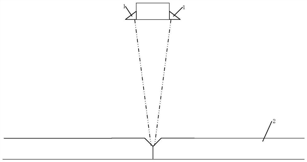
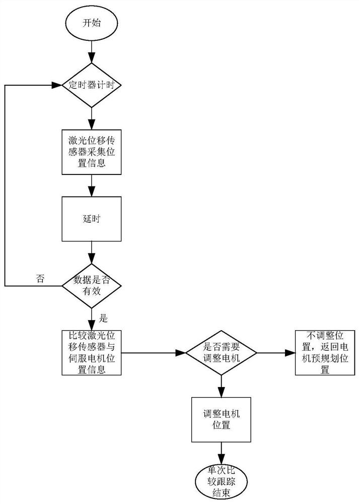

Image

  • Method of detecting cladding quality based on laser displacement sensor coaxial powder feeding equipment
  • Method of detecting cladding quality based on laser displacement sensor coaxial powder feeding equipment
  • Method of detecting cladding quality based on laser displacement sensor coaxial powder feeding equipment

Examples


Embodiment Construction

[0025] In order to make the object, technical solution and advantages of the present invention more clear, the present invention will be further described in detail below in conjunction with the embodiments and accompanying drawings. Those skilled in the art should know that the following specific embodiments or specific implementation methods are a series of optimized configurations listed by the present invention to further explain the specific content of the invention, and these configurations can be combined with each other or mutually Used in association, unless it is clearly stated in the present invention that some or a specific embodiment or implementation cannot be associated with or used in conjunction with other embodiments or implementations. At the same time, the following specific examples or implementation methods are only used as optimized configurations, and are not understood as limiting the protection scope of the present invention.

[0026] In addition, tho...


PUM


Abstract

The invention relates to a method for detecting cladding quality based on a coaxial powder feeding device of a laser displacement sensor, comprising the following steps: firstly, a servo motor moves according to a motion trajectory specified by a processing program; The actual coordinate position of the cladding head relative to the cladding workpiece is first compared with the position of the workpiece signal monitored by the laser displacement sensor to determine whether the position deviation of the two exceeds the deviation range of the signal collected by the laser displacement sensor set in advance, and the signal processing is performed automatically; At the same time, the controller compares the actual coordinate position of the cladding head relative to the cladding workpiece fed back by the servo motor encoder with the pre-planned command position of the servo motor to determine whether the position deviation between the two exceeds the pre-set servo motor automatic adjustment. The deviation range is automatically adjusted for the servo motor. The detection method of the present invention can realize ultra-stable and high-precision measurement for all workpieces that are difficult to detect.

Description

technical field [0001] The invention belongs to the technical field of additive manufacturing, and in particular relates to a method for detecting cladding quality based on laser displacement sensor coaxial powder feeding equipment. Background technique [0002] Coaxial powder feeding laser cladding technology is an important development direction of laser rapid prototyping technology. According to different powder feeding methods, laser rapid prototyping equipment can be divided into two main technical directions: powder spreading type and coaxial powder feeding type cladding technology. . The powder spreading device of the powder spreading 3D printing equipment includes a powder storage chamber, a powder spreading shaft and a scraper. In the printing area of ​​the workpiece, the path scanned by the laser is solidified into a solid structure, and then the substrate in the printing area is lowered to a certain height, and the scraper will The 3D printing metal powder in the...

Claims


Application Information

Patent Timeline
Patent Type & Authority Patents(China)
IPC IPC(8): G01B11/245G01B11/00C23C24/10B33Y40/00
CPCB33Y40/00C23C24/103G01B11/002G01B11/24
Inventor 尚玮关凯周峰
Owner 天津镭明激光科技有限公司
Learn More