Demolding device capable of being used for molding

A technology of demolding device and mounting plate, which is applied in measurement devices, preparation of test samples, analysis of suspensions and porous materials, etc. The effect of small wear and simple structure

Pending Publication Date: 2020-04-24
安徽省建筑工程质量监督检测站有限公司皖南分站
View PDF0 Cites 0 Cited by
  • Summary
  • Abstract
  • Description
  • Claims
  • Application Information

AI Technical Summary

Problems solved by technology

[0002] In the laboratory, it is often necessary to test the anti-seepage test block to carry out the test piece work (commonly known as: the upper mold), after the test, the specimen needs to be taken out from the anti-seepage mold (commonly known as: demoulding), and the demoulding work is also common. For various tests such as compaction test of geotechnical test and asphalt mixture, before the anti-seepage test, it is often necessary to carry out mold work on the anti-seepage detection part. After the test is completed, it is necessary to demould the test part. The existing demoulding The device only relies on the pneumatic method to eject the test piece from the mold from bottom to top; there are also some demoulding devices that rely on the rotating stud to push the test piece out, but this device is due to the vertical movement at the same time Rotation, because if the device is used on the upper mold, it will cause friction and rotation between the test piece and the inner wall of the mold, resulting in wear of the test piece and affecting the test results, so this type of device is only suitable for demoulding work

Method used


Image

  • Demolding device capable of being used for molding
  • Demolding device capable of being used for molding
  • Demolding device capable of being used for molding

Examples


Embodiment Construction

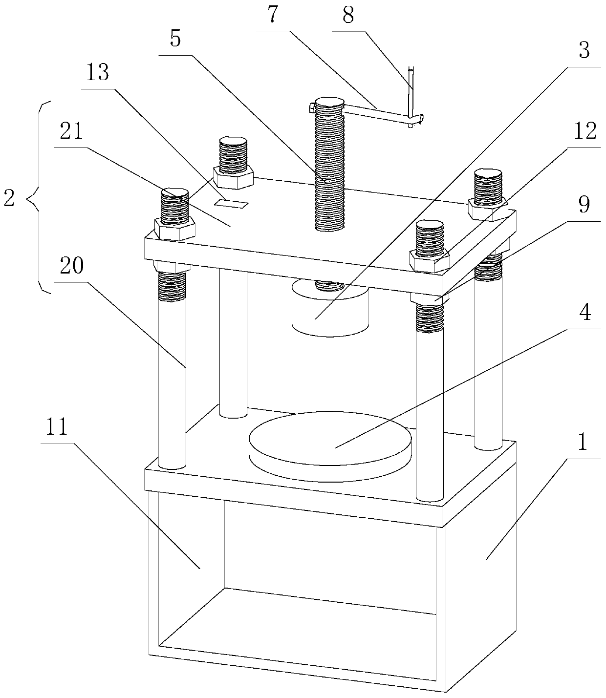
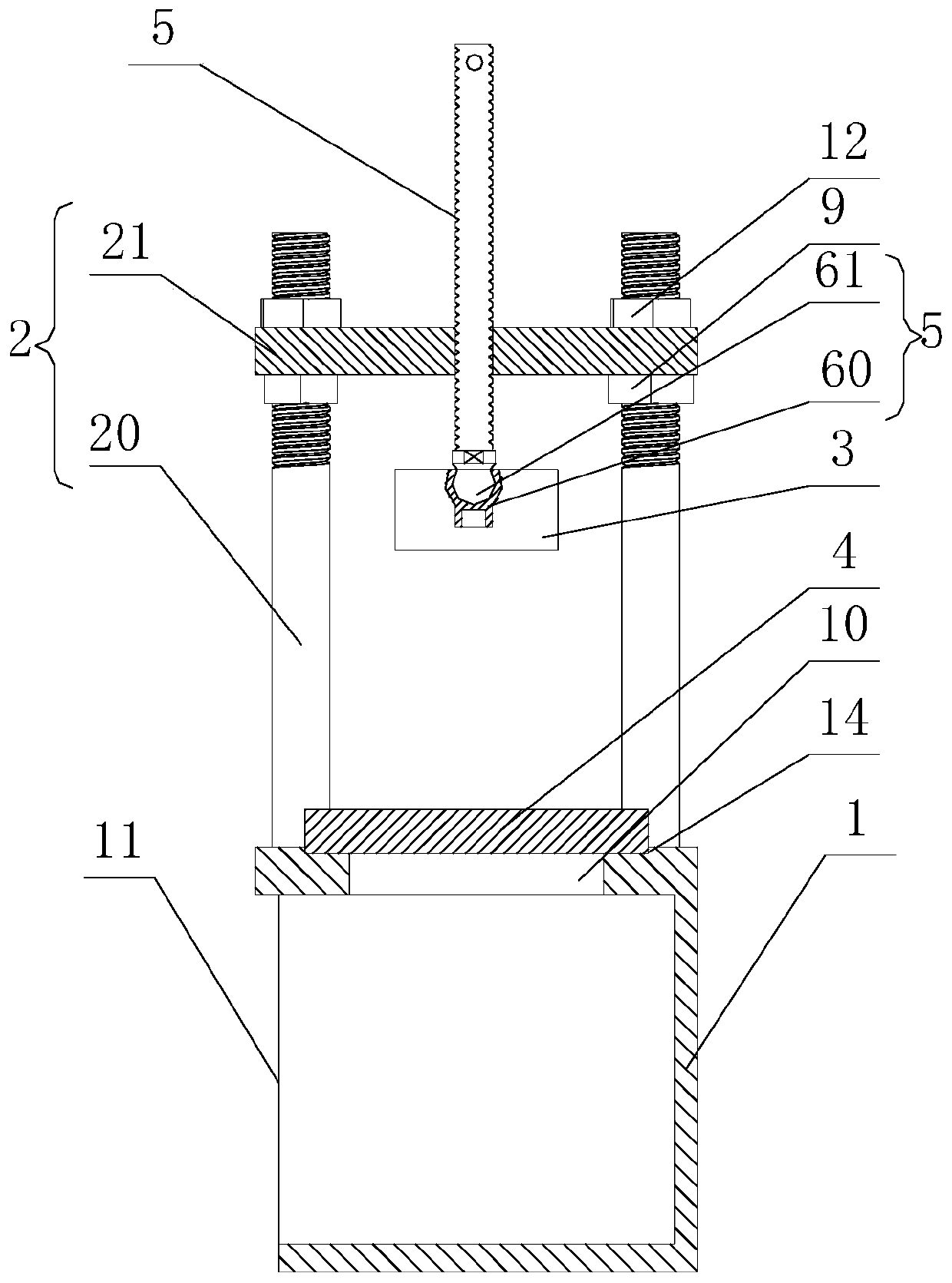
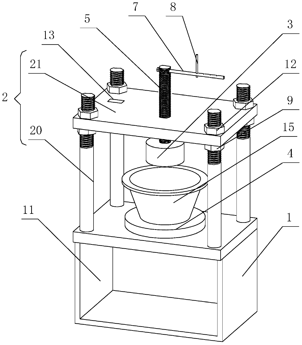
[0021] Embodiments of the present invention are described in detail below, examples of which are shown in the drawings, wherein the same or similar symbols designate the same or similar elements or elements having the same or similar functions throughout. The embodiments described below by referring to the figures are exemplary only for explaining the present invention and should not be understood as limiting the present invention.

[0022] It is to be understood that the terms "center", "longitudinal", "transverse", "length", "width", "thickness", "upper", "lower", "front", "rear", "left", "Right", "Vertical", "Horizontal", "Top", "Bottom", "Inner", "Outer", "Clockwise", "Counterclockwise", "Axial", "Radial", "Circumferential" The orientation or positional relationship indicated to ", etc. is based on the orientation or positional relationship shown in the drawings, which is only for the convenience of describing the present invention and simplifying the description, rather t...


PUM


Abstract

The invention discloses a demolding device capable of being used for molding. The demolding device comprises a box body, a bracket, a pressurizing plate, a feeding base plate and a stud, wherein a blanking port is formed in the top plate of the box body, the feeding base plate is detachably installed on the box body and used for sealing the blanking port, the bracekt is installed on the box body,the stud is vertically installed on the braclet in a threaded mode, the pressurizing plate is rotatably installed at the bottom of the stud, and the stud rotates to drive the pressurizing plate to move in the direction close to or away from the top plate of the box body. The demolding device is simple in structure and convenient to realize demolding and molding of the inspection piece. In the demolding and molding process, the pressurizing plate is rotationally connected with the stud, after the pressurizing plate abuts against the detection piece and the stud rotates downwards, the pressurizing plate does not rotate, then the detection piece is prevented from rotating relative to the mold and abrasion of the detection piece is reduced.

Description

technical field [0001] The invention relates to the technical field of demoulding devices in the test process of construction, water conservancy, transportation and other industries, in particular to a demoulding device that can be used for upper molds. Background technique [0002] In the laboratory, it is often necessary to test the anti-seepage test block to carry out the test piece work (commonly known as: the upper mold), after the test, the specimen needs to be taken out from the anti-seepage mold (commonly known as: demoulding), and the demoulding work is also common. For various tests such as compaction test of geotechnical test and asphalt mixture, before the anti-seepage test, it is often necessary to carry out mold work on the anti-seepage detection part. After the test is completed, it is necessary to demould the test part. The existing demoulding The device only relies on the pneumatic method to eject the test piece from the mold from bottom to top; there are al...

Claims


Application Information

Patent Timeline
IPC IPC(8): G01N15/08G01N1/28
CPCG01N1/28G01N15/0806
Inventor 王林华孔昊泉朱甲龙王晓泉谢全全姚进王后水
Owner 安徽省建筑工程质量监督检测站有限公司皖南分站
Why Eureka
Try Eureka