Outer rotor motor applied to robot arm and robot arm

A technology of outer rotor motor and robot arm, which can be applied to electromechanical devices, casings/covers/supports, electrical components, etc., and can solve the problems of large size of outer rotor motors.

Pending Publication Date: 2020-04-24
珠海恒力源机电有限公司
View PDF0 Cites 2 Cited by
  • Summary
  • Abstract
  • Description
  • Claims
  • Application Information

AI Technical Summary

Problems solved by technology

[0004] The present invention makes improvements to the problem that the outer rotor motor on the robot arm of the above prior art has a large volume and takes up space. The technical problem to be solved by the present invention is to provide an outer rotor motor applied on the robot arm

Method used


Image

  • Outer rotor motor applied to robot arm and robot arm
  • Outer rotor motor applied to robot arm and robot arm
  • Outer rotor motor applied to robot arm and robot arm

Examples


Embodiment Construction

[0028] In order to make the technical problems, technical solutions and beneficial effects solved by the present application clearer, the present application will be further described in detail below in conjunction with the accompanying drawings and embodiments. It should be understood that the specific embodiments described here are only used to explain the present application, not to limit the present application.

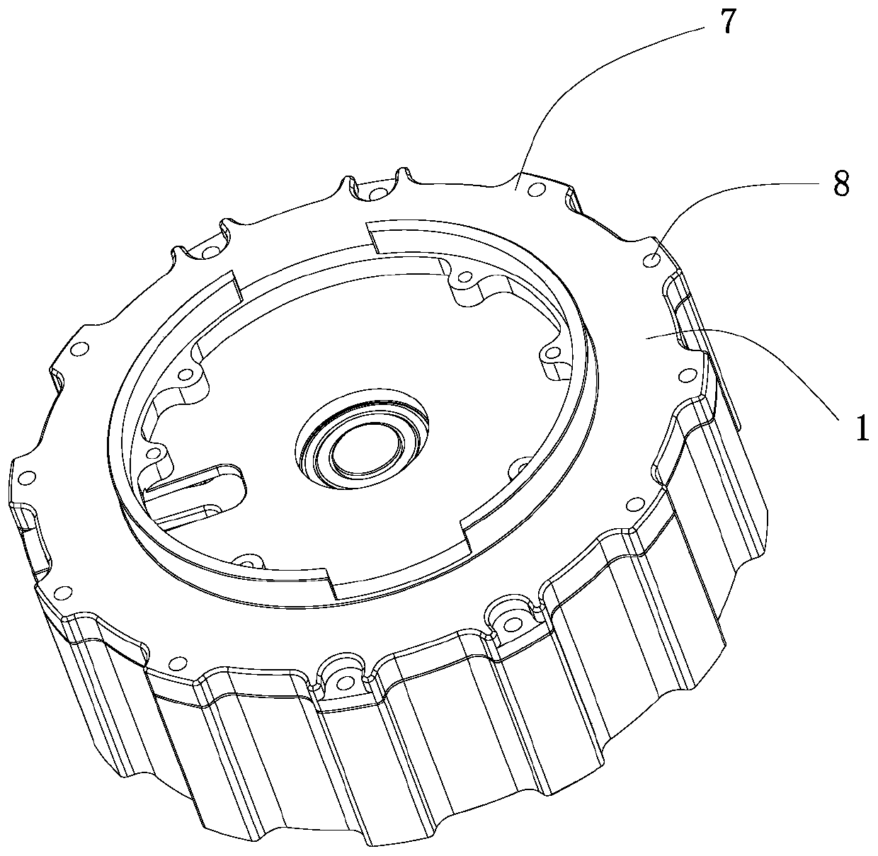
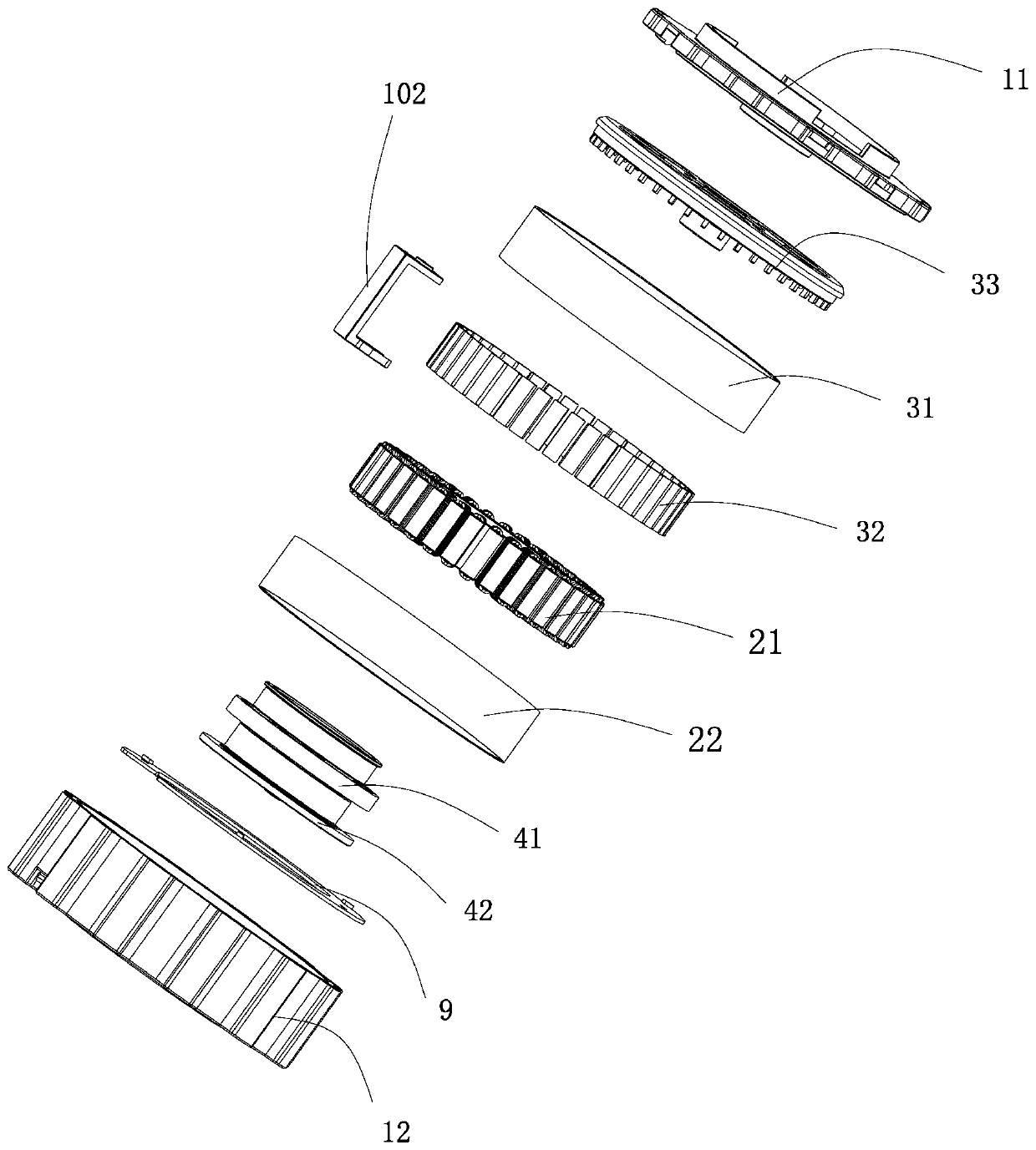
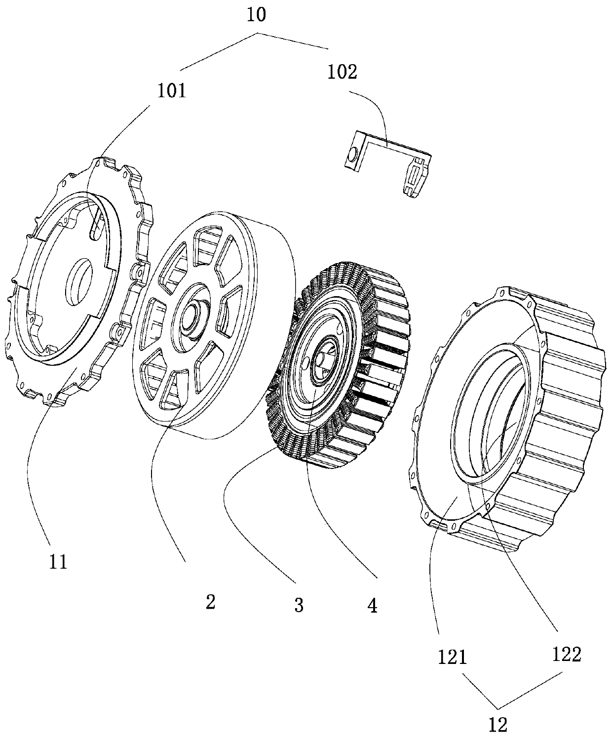
[0029] Depend on Figure 1-Figure 3 The shown external rotor motor applied on the robot arm can be known to include a casing 1, a stator group 2 is arranged inside the casing 1, a rotor group 3 is arranged on the outside of the stator group, and a rotor group 3 is arranged on the inside of the stator group 2. There is a reduction group 4 connected with the rotor group 3 to reduce the speed of the rotor group 3. The reduction group 4 includes a planetary reduction group 41 with one end connected to the rotor group 3 and a transmission connection between the planet...


PUM


Abstract

The invention discloses an outer rotor motor applied to a robot arm and the robot arm. The outer rotor motor comprises a shell, a stator set arranged in the shell, and a rotor set arranged on the outer side of the stator set. A speed reduction set which is in transmission connection with the rotor set and used for reducing the rotating speed of the rotor set is arranged on the inner side of the stator set. By the adoption of the structure in which the speed reduction set is arranged in the outer rotor motor, the output rotating speed of the rotor set is reduced, meanwhile, the inner space is optimized, the motor is lightened and thinned, and the outer rotor motor can be conveniently applied to the fields with high requirements for size and structure limitation, such as robot arms and joints.

Description

【Technical field】 [0001] The present application relates to the technical field of motor manufacturing, in particular to an outer rotor motor applied to a robot arm and the robot arm. 【Background technique】 [0002] With the rapid development of IC, semiconductor, and 3C industries, modern automated factories continue to upgrade, industrial robots will be more widely used in various fields of manufacturing, and the requirements for robots in the field of precision assembly are getting higher and higher. [0003] In the existing external rotor motor applied on the robot arm, a reduction box is usually connected to the output end of the external rotor motor to achieve the purpose of reducing transmission and increasing torque. The structure of adding a reduction box at the output end of the outer rotor motor undoubtedly takes up the space of the robot arm, which is not conducive to the optimal use of the space of the robot arm. 【Content of invention】 [0004] The present in...

Claims


Application Information

Patent Timeline
Patent Type & Authority Applications(China)
IPC IPC(8): H02K7/10H02K7/116H02K11/215H02K11/00H02K5/22H02K1/28
CPCH02K1/28H02K5/225H02K7/10H02K7/116H02K11/0094H02K11/215
Inventor 郭安才刘威力何衍青邹冬华
Owner 珠海恒力源机电有限公司
Why Eureka
Try Eureka