Suction cleaning device with chamber cover with locking device

A technology for cleaning equipment and locking devices, which is applied to cleaning equipment, suction nozzles, vacuum cleaners, etc., and can solve problems such as high manufacturing costs

Active Publication Date: 2020-04-28
VORWERK & CO INTERHOLDING GMBH
View PDF6 Cites 0 Cited by
  • Summary
  • Abstract
  • Description
  • Claims
  • Application Information

AI Technical Summary

Problems solved by technology

[0005] Although the locking devices known in the prior art for suction cleaning devices have proven to be suitable, such locking devices require high manufacturing effort because there are many different components on the chamber cover and the filter chamber. Components that interact for the locking function

Method used


Image

  • Suction cleaning device with chamber cover with locking device
  • Suction cleaning device with chamber cover with locking device
  • Suction cleaning device with chamber cover with locking device

Examples


Embodiment Construction

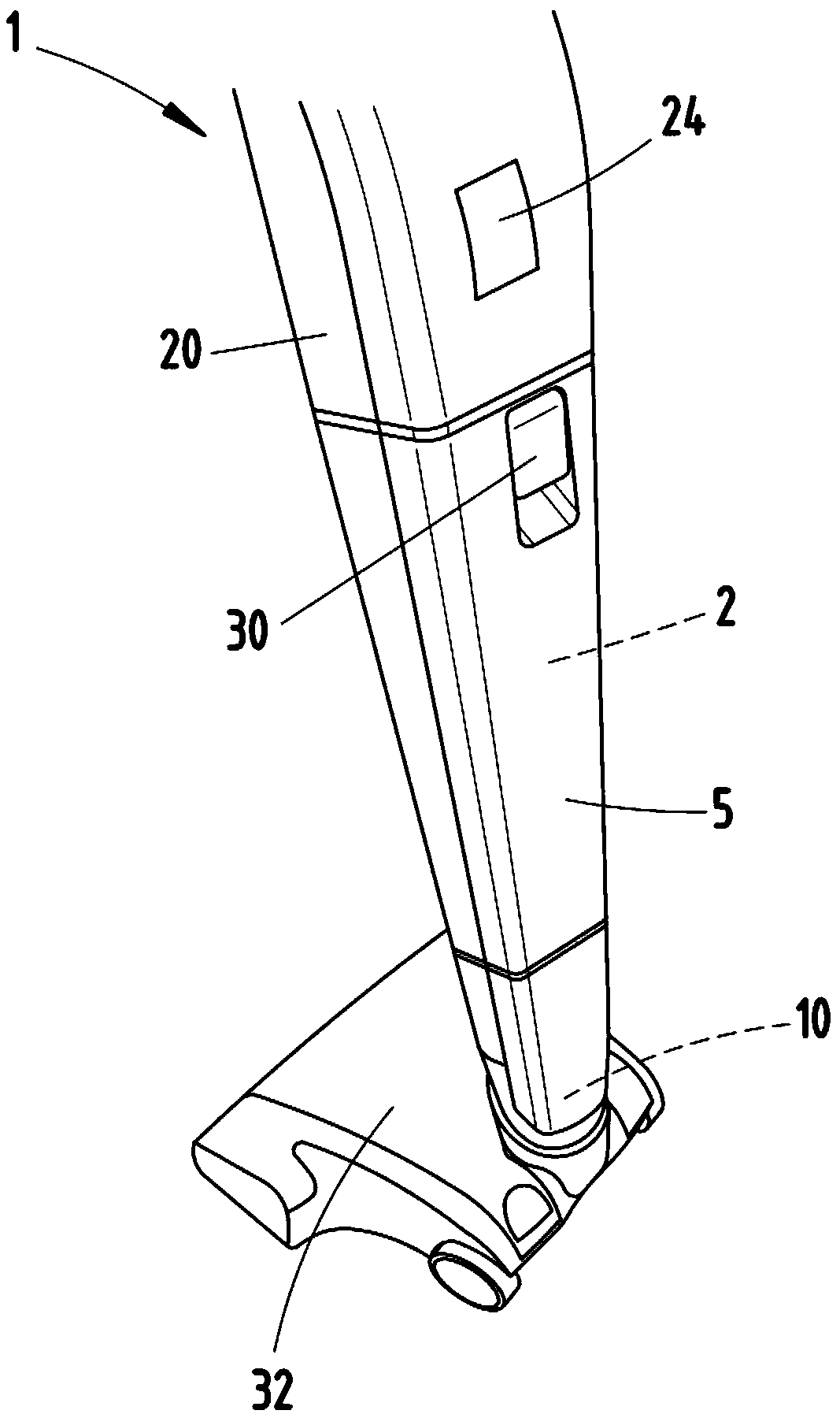
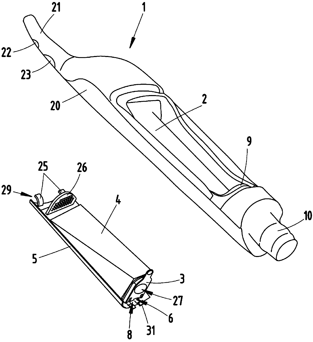
[0028] figure 1 An extraction cleaning device 1 according to the invention is shown, which is designed here, for example, as a battery-operated vacuum cleaner. The suction cleaning device 1 has a housing 20 with a shaped handle 21 (see figure 2 ) for guiding the suction cleaning device 1 by the user. On the side of the suction cleaning device 1 facing away from the handle 21 , the housing 20 has a suction connection 10 to which an accessory, here for example a bottom suction nozzle 32 , is connected. The suction cleaning device 1 has a motor-fan unit, not shown in detail, which is used to suck suction material into the suction cleaning device 1 . On the handle 21 there is a switch 22 for switching on and off the motor-fan unit and a selector switch 23 , by which different power levels of the motor-fan unit can be selected. Furthermore, a display device 24 is located on the housing 20 of the suction cleaning appliance 1 , which displays the state of charge of the battery of...


PUM


Abstract

The invention relates to a suction cleaning device (1). The suction cleaning device is provided with a filter cavity (2) and a filter bag (4) with a holding plate (3). The filter cavity (2) is provided with a cavity cover (5), the cavity cover (5) is provided with a locking device (6) with a spring element (7) on the inner side pointing to the filter cavity (2), the locking device (6) is arrangedand designed to be adapted to the holding plate (3) of the filter bag (4) in such a way that the cavity cover (5) can be moved into the closed state of the filter cavity (2) only when the holding plate (3) of the filter bag (4) displaces the locking device (6) against the restoring force of the spring element (7) into the release position. The aim of the invention is to advantageously improve thesuction cleaning device (1). Proposed herein is a suggestion, the locking device (6) is arranged on a cover edge region (8) of the cavity cover (5), the cover edge region (8) can engage a cavity edgeregion (9) of the filter cavity (2) in order to close the filter cavity (2), the locking device (6) is designed and arranged to be adapted to the cavity edge region (9) in such a way that, in a preferred position corresponding to the relaxed state of the spring element (7), the locking device (6) impacts the cavity edge region (9) and prevents the cover edge region (8) from engaging with the cavity edge region (9).

Description

technical field [0001] The invention relates to a suction cleaning device with a filter chamber and a filter bag with a holding plate, wherein the filter chamber has a chamber cover, which has a locking device with a spring element on the inner side pointing towards the filter chamber, wherein , the locking device and the holding plate of the filter bag are arranged and designed so that the chamber cover can only move when the holding plate of the filter bag overcomes the restoring force of the spring element and moves the locking device to the release position to the closed state of the filter cavity. Background technique [0002] Suction cleaning devices of the above-mentioned type are well known in the prior art. Such suction cleaning devices can be, for example, hand-held vacuum cleaners or self-propelled vacuum cleaners. The suction cleaning appliance can have a battery for energy supply or alternatively be powered via the domestic electrical network. In order to be ...

Claims


Application Information

Patent Timeline
IPC IPC(8): A47L9/02A47L9/00
CPCA47L9/02A47L9/00A47L9/14A47L9/122A47L9/1436A47L9/1427A47L9/2857
Inventor H-P.阿诺德B.萨利斯钟瑜M.塞尔奈奇
Owner VORWERK & CO INTERHOLDING GMBH
Why Eureka
Try Eureka