Fire fighting truck boom device and fire fighting truck

A fire truck and boom technology, which is applied in the field of fire truck boom devices and fire trucks, can solve the problems of unfavorable long-distance water spraying, limited expansion and contraction of conveying pipes, and difficulty in controlling the direction of the exit of conveying pipes.

Inactive Publication Date: 2020-04-28
SANY AUTOMOBILE MFG CO LTD
View PDF5 Cites 4 Cited by
  • Summary
  • Abstract
  • Description
  • Claims
  • Application Information

AI Technical Summary

Problems solved by technology

[0002] At present, most of the boom devices assembled on firefighting vehicles use hydraulic cylinders to drive the bottom section of the boom to rotate and drive the water pipes to rotate. However, the layout of this structure has limitations, and the length of the bottom section of the boom is limited, which is not conducive to long-distance water spraying operations.
In the prior art, there is provided a telescopic boom, the telescopic oil cylinder is provided on the distal boom, and the telescopic piece is provided on the water pipe corresponding to the distal boom, so that the telescopic cylinder on the distal boom drives the conveying pipe to expand and contract synchronously, so as to Increase the length of the terminal boom and the delivery pipe, but the expansion and contraction of the delivery pipe of the terminal boom in this scheme is limited, and the outlet direction of the delivery pipe is not easy to control, and the accuracy of the spray direction is low when applied to fire trucks

Method used


Image

  • Fire fighting truck boom device and fire fighting truck
  • Fire fighting truck boom device and fire fighting truck
  • Fire fighting truck boom device and fire fighting truck

Examples


Embodiment 1

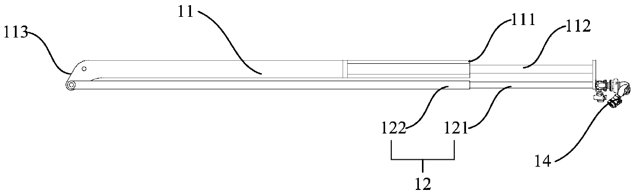
[0043] Provided in this embodiment is a fire truck boom device 1, such as figure 1 As shown, the fire engine boom device 1 includes a support arm 11 , a telescoping water pipe 12 and a spray gun assembly 14 . The support arm 11 includes a first end 111 and a second end 113 located in the length direction, the first end 111 is fixedly provided with a telescopic oil cylinder 112, and the telescopic direction of the telescopic oil cylinder 112 is set along the length direction of the support arm 11, so that the telescopic oil cylinder 112 It can expand and contract relative to the first end 111 along the length direction of the support arm 11 . The telescopic water pipe 12 includes a first pipe section 121 and a second pipe section 122 , the first pipe section 121 and the second pipe section 122 are socketed together, and the first pipe section 121 can extend or retract relative to the second pipe section 122 . The first pipe section 121 and the second pipe section 122 extend al...

Embodiment 2

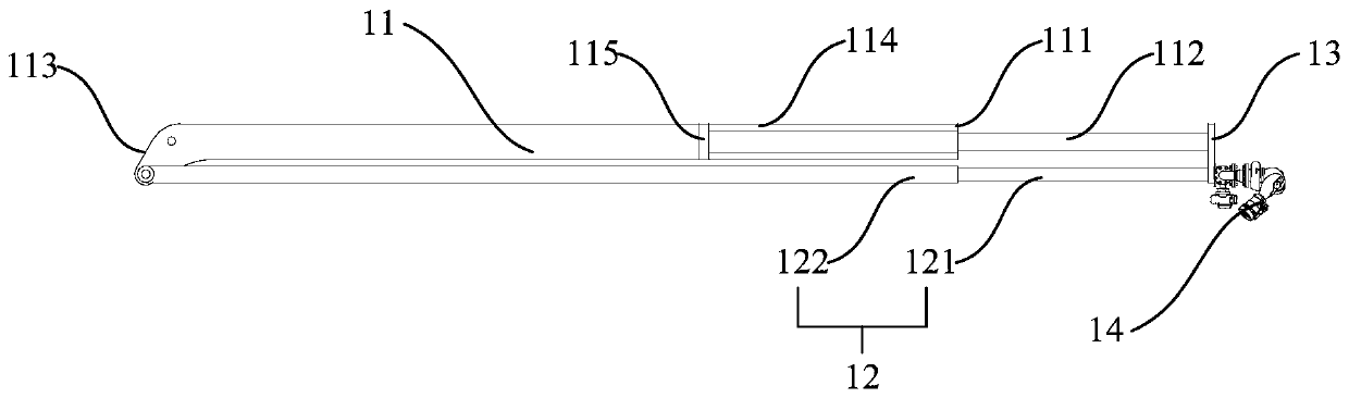
[0045] Provided in this embodiment is a fire truck boom device 1, such as figure 2 As shown, the fire engine boom device 1 includes a support arm 11 , a telescoping water pipe 12 and a spray gun assembly 14 . The first end 111 of the support arm 11 forms a cylindrical inner cavity 114 with an opening, and an inner connector 115 is fixed at the end of the cylindrical inner cavity 114 away from the opening; The cylinder barrel of the oil cylinder 112 is arranged in the cylindrical inner cavity 114 and is connected with the inner connector 115. One end of the piston rod of the telescopic oil cylinder 112 faces the open end of the cylindrical inner cavity 114, and can be directed toward the cylindrical inner cavity 114. Extend outward or retract inward. The telescopic water pipe 12 includes a first pipe section 121 and a second pipe section 122. The second pipe section 122 is sheathed on the outside of the first pipe section 121 and communicates with the first pipe section 121. ...

Embodiment 3

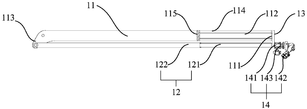
[0048] The fire engine boom device provided in this embodiment is further improved on the basis of the second embodiment. Such as image 3 As shown, the spray gun assembly 14 specifically includes a connecting seat 141, a spray gun 142 and a connecting pipe 143. The two ends of the connecting seat 141 are detachably connected to the flange connector 13 and the spray gun 142 respectively, and the spray gun 142 can be moved relative to the connecting seat 141. Rotate to change the water spraying direction by the rotation of the spray gun 142 when the spray gun assembly 14 performs the water spray operation. Both ends of the connecting pipe 143 communicate with the spray gun 142 and the first pipe section 121 of the telescopic water pipe 12 , so that the spray gun 142 communicates with the telescopic water pipe 12 .

[0049] Further, the telescopic stroke of the telescopic water pipe 12 is the same as the telescopic stroke of the piston rod of the telescopic oil cylinder 112, an...


PUM


Abstract

The invention provides a fire-fighting truck boom device and a fire-fighting truck. The fire-fighting truck boom device comprises a support arm, a telescopic water pipe and a spray gun assembly; the support arm comprises a first end and a second end in the length direction, the first end is fixedly provided with a telescopic oil cylinder, and the telescopic direction of the telescopic oil cylinderis arranged in the length direction of the support arm; the telescopic water pipe comprises a first pipe section and a second pipe section, the second pipe section and the first pipe section are sleeved with each other, and the first pipe section can extend or retract outwards relative to the second pipe section; the spray gun assembly is connected with one end, away from the second pipe section,of the first pipe section, wherein the second pipe section is connected with the support arm, the first pipe section is connected with the telescopic end of the telescopic oil cylinder, and the telescopic oil cylinder is used for driving the first pipe section to extend out of a predetermined distance of the first end of the support arm in the length direction of the support arm. According to thetechnical scheme, the space arrangement of the fire-fighting truck boom device is optimized, and the extension length of the fire-fighting truck boom device and the operation range of the spray gun assembly are increased under the condition that the overall size is not influenced.

Description

technical field [0001] The invention relates to the technical field of fire protection, in particular to a fire truck boom device and a fire truck. Background technique [0002] At present, the boom devices assembled on fire-fighting vehicles mostly use hydraulic cylinders to drive the bottom section of the boom to rotate and drive the water pipes to rotate. However, the layout of this structure has limitations, and the length of the bottom section of the boom is limited, which is not conducive to long-distance water spraying operations. In the prior art, there is provided a telescopic boom, the telescopic oil cylinder is provided on the distal boom, and the telescopic piece is provided on the water pipe corresponding to the distal boom, so that the telescopic cylinder on the distal boom drives the conveying pipe to expand and contract synchronously, so as to Increase the length of the terminal boom and the delivery pipe, but the expansion and contraction of the delivery pip...

Claims


Application Information

Patent Timeline
Patent Type & Authority Applications(China)
IPC IPC(8): A62C27/00
CPCA62C27/00
Inventor 邓彪许伟陈志伟
Owner SANY AUTOMOBILE MFG CO LTD
Why Eureka
Try Eureka