
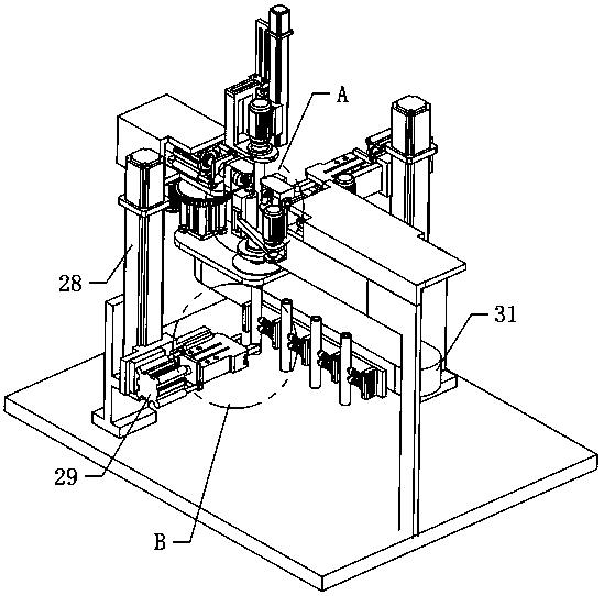
Fishing gig handle preassembly correction mechanism

A calibration mechanism and pre-assembly technology, applied in metal processing, metal processing equipment, manufacturing tools, etc., can solve the problems of increased labor costs, time-consuming and labor-intensive, and inability to achieve automated production.

Active Publication Date: 2020-04-28
罗碧波
View PDF5 Cites 1 Cited by
  • Summary
  • Abstract
  • Description
  • Claims
  • Application Information

AI Technical Summary

Problems solved by technology

[0002] The fork shank is a connecting piece used to connect the harpoon head and the fork shaft in the fishing fork tool. Generally, the fork handle is cylindrical, and at least one along the fork is opened on its outer surface (the middle section area) The threaded hole through which the radial direction of the shank passes through is used to connect the fork handle and the fork head with bolts; the part connecting the fork head and the fork handle of the fishing fork is a metal outer frame It needs to be bent through at least two steps before it can be formed. In the process of connecting with the fork handle, the metal frame needs to be compressed by pressing equipment. Before pressing, the fork handle is sent into the metal frame, so in the process of pressing In the process, the fork handle and the metal frame will be in close contact, and then the bolts are manually installed, so during the assembly process of the fork handle, its upper assembly posture must be fixed, that is, the direction of the threaded hole is fixed in one direction, so that it can be realized Assembly; since the fork handle is cylindrical, its posture will change after it is processed and formed. Before the assembly work after the subsequent conveying process, it is necessary to manually correct the fork handle to the preset posture in advance. Such an operation is time-consuming and laborious, causing enterprises The cost of employment increases, and automatic production cannot be realized

Method used


Image

  • Fishing gig handle preassembly correction mechanism
  • Fishing gig handle preassembly correction mechanism
  • Fishing gig handle preassembly correction mechanism

Examples


Embodiment Construction

[0044] The technical solutions of the present invention will be further described below in conjunction with the accompanying drawings and through specific implementation methods.

[0045] Wherein, the accompanying drawings are only for illustrative purposes, showing only schematic diagrams, rather than physical drawings, and should not be construed as limitations on this patent; in order to better illustrate the embodiments of the present invention, some parts of the accompanying drawings will be omitted, Enlargement or reduction does not represent the size of the actual product; for those skilled in the art, it is understandable that certain known structures and their descriptions in the drawings may be omitted.

[0046] In the drawings of the embodiments of the present invention, the same or similar symbols correspond to the same or similar components; , "inner", "outer" and other indicated orientations or positional relationships are based on the orientations or positional ...


PUM


Abstract

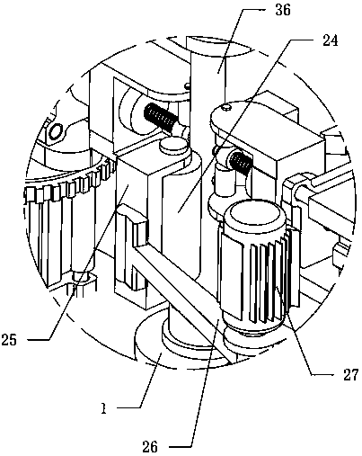
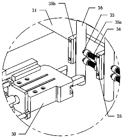
The invention relates to the technical field of fishing gig assembly, in particular to a fishing gig handle preassembly correction mechanism. The mechanism comprises a support plate, a pressing plate,a rotation driving plate and a detection mechanism. The support plate can be vertically and movably arranged through a first lifting mechanism, the pressing plate can be vertically and movably arranged over the support plate through a second lifting mechanism, a positioning area is formed between the pressing plate and the support plate, the rotation driving plate can rotate around the axis of the rotation driving plate and is arranged above the pressing plate, and the rotation driving plate also can be vertically and movably arranged through a third lifting mechanism. The detection mechanismcomprises two elastic pieces symmetrically arranged outside the positioning area, the ends, opposite to each other, of the two elastic pieces are each provided with a positioning ball, and the otherends of the two elastic pieces are each provided with a distance measuring sensor. When the elastic pieces are in a normal state, the positioning balls in the corresponding state can be located in thepositioning area, and two first guide rollers which are vertical are also symmetrically arranged outside the positioning area. A gig handle can be automatically corrected through the mechanism, and the use cost is further reduced for personnel .

Description

technical field [0001] The invention relates to the technical field of harpoon assembly, in particular to a pre-assembly correction mechanism for a harpoon handle. Background technique [0002] The fork shank is a connecting piece used to connect the harpoon head and the fork shaft in the fishing fork tool. Generally, the fork handle is cylindrical, and at least one along the fork is opened on its outer surface (the middle section area) The threaded hole through which the radial direction of the shank passes through is used to connect the fork handle and the fork head with bolts; the part connecting the fork head and the fork handle of the fishing fork is a metal outer frame It needs to be bent through at least two steps before it can be formed. In the process of connecting with the fork handle, the metal frame needs to be compressed by pressing equipment. Before pressing, the fork handle is sent into the metal frame, so in the process of pressing In the process, the fork h...

Claims


Application Information

Patent Timeline
IPC IPC(8): B23P19/00
CPCB23P19/00
Inventor 彭正飞
Owner 罗碧波
Learn More