
Tubular product cutting device with polishing function

A cutting device and pipe material technology, applied to machine tools, grinders, manufacturing tools, etc., which are suitable for grinding the edge of workpieces, can solve the problems of time-consuming and labor-consuming, prolong production time, etc., and achieve the reduction of beating, avoiding beating, and stable support and the effect of limit

Active Publication Date: 2020-04-28
重庆泓通管业有限公司
View PDF5 Cites 20 Cited by
  • Summary
  • Abstract
  • Description
  • Claims
  • Application Information

AI Technical Summary

Problems solved by technology

In the process of transporting the cut pipes to the grinding room, workers are required to load and unload materials, which is very time-consuming and labor-intensive, greatly prolonging the entire production time

Method used


Image

  • Tubular product cutting device with polishing function
  • Tubular product cutting device with polishing function
  • Tubular product cutting device with polishing function

Examples


Embodiment 1

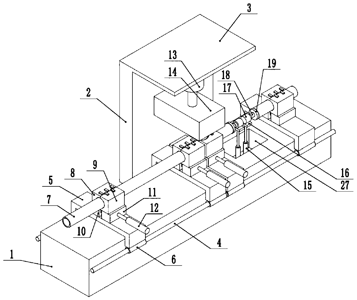
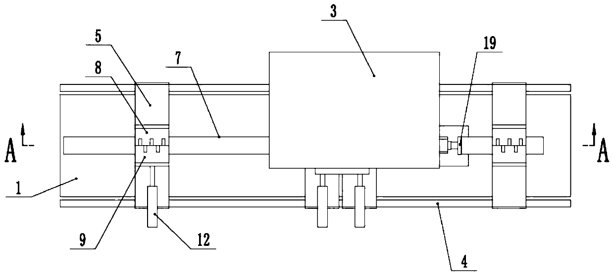
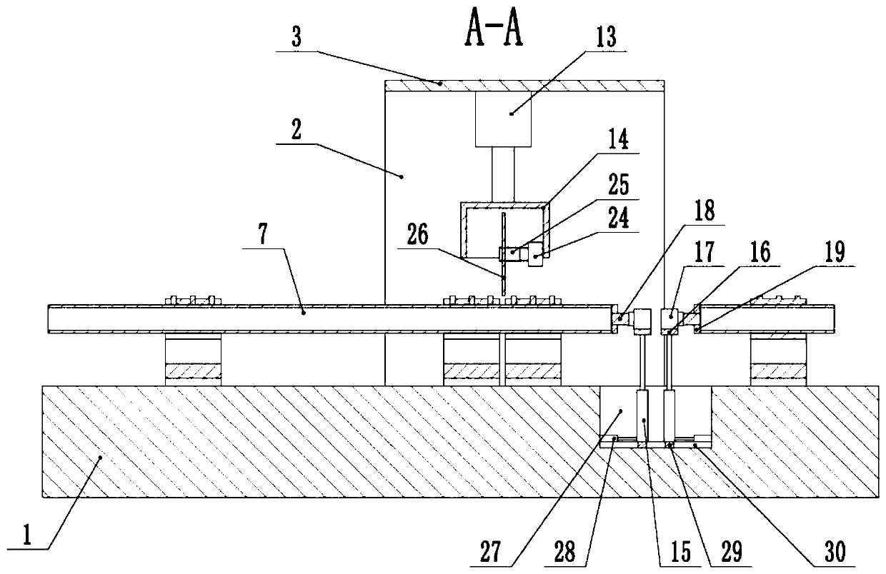
[0037] The embodiment is basically as attached figure 1 Shown: a pipe cutting device with a grinding function, including a worktable 1, the workbench 1 is a cuboid structure, and the workbench 1 is sequentially provided with a transmission unit, a clamping unit and a retrieving unit along the transmission direction of the pipe 7, and the transmission The structure of the unit, gripping unit and retrieving unit is identical. A cutting unit is provided above the clamping unit, and a grinding unit is provided on the side of the clamping unit close to the material taking unit.

[0038] In this embodiment, two clamping units are provided, and the two clamping units are arranged parallel to each other. The clamping unit, the conveying unit and the retrieving unit all include a sliding table 5, and the two ends of the sliding table 5 are aligned with the conveying direction of the pipe. Both sides of workbench 1 are slidingly connected. In this embodiment, guide rails 4 are welded an...

Embodiment 2

[0050] Such as Figure 4 and Figure 5 As shown, a pipe cutting device with a grinding function differs from Embodiment 1 in that an installation cavity 31 is provided on the workbench 1, and the installation cavity 31 is located between the retrieving unit and the storage cavity 27, and the installation cavity 31 A discharge cylinder 22 is provided, the bottom of the discharge cylinder 22 is fixed to the bottom of the installation chamber 31 by bolts, the output shaft of the discharge cylinder 22 is fixedly connected with a discharge plate 23 by bolts, and the discharge plate 23 is vertical to the pipe material 7 Right on set.

[0051] In this embodiment, the longitudinal section of the unloading plate 23 is arc-shaped, and one end of the unloading plate 23 with an arc surface is arranged opposite to the pipe material 7. A material guide plate 20 is arranged on the workbench 1, and the material guide plate 20 is located at the On the right side of the material unit, the mat...


PUM


Abstract

The invention belongs to the technical field of cutting equipment, and particularly discloses a tubular product cutting device with a polishing function. The tubular product cutting device comprises aworking table, and the working table is provided with a cutting unit, two clamping units and polishing units. The clamping units comprise sliding tables, and two ends of the sliding tables are slidably connected with the two sides of the working table in the conveying direction of a tubular product. Fixed clamps and movable clamps are arranged at the top ends of the sliding tables, wherein the fixed clamps and the movable clamps are mutually symmetric, the fixed clamps are fixedly connected with the sliding tables, and the movable clamps are slidably connected with the sliding tables. First power pieces for driving the movable clamps to slide are arranged on the sliding tables, the polishing units comprise polishing discs and second power pieces for driving the polishing discs to performreciprocating motion in the vertical direction, and a storage cavity for storing the polishing discs is formed in the working table. According to the tubular product cutting device with the polishingfunction, the tubular product is cut, meanwhile, the end part of the tubular product is polished, so that machining is carried out without being divided into two steps, and the machining efficiency isimproved.

Description

technical field [0001] The application of the present invention belongs to the technical field of cutting equipment, and specifically discloses a pipe cutting device with a grinding function. Background technique [0002] At present, when manufacturers produce controlled products, they need to cut the pipes into the size specifications that meet the product requirements. At present, the main way to cut the pipes is to place the pipes on the workbench, and the workbench is equipped with a cutting knife. The feeding motion of the drive and the rotating motion of the cutting knife are used to cut the pipe. The end of the cut pipe usually has burrs. Therefore, in order to improve the quality of the pipe, the manufacturer usually needs to transport the cut pipe to a special grinding room for the pipe. The end of the pipe is ground to improve the flatness and smoothness of the end of the pipe, thereby improving the quality of the pipe. In the process of transporting the cut pipes...

Claims


Application Information

Patent Timeline
IPC IPC(8): B26D1/16B26D7/02B26D7/20B24B9/00
CPCB24B9/007B26D1/16B26D7/02B26D7/20B26D2007/013
Inventor 付志敏姜通均宋理
Owner 重庆泓通管业有限公司
Features
  • Generate Ideas
  • Intellectual Property
  • Life Sciences
  • Materials
  • Tech Scout
  • Unparalleled Data Quality
  • Higher Quality Content
  • 60% Fewer Hallucinations
Learn More