

Plastic particle raw material screening machine
A technology for plastic granules and screening machines, applied in the field of screening machines, can solve the problems of high sorting accuracy, oversized equipment, inconvenient fixing and dismantling, etc., and achieves the effects of facilitating dispersed collection, preventing clogging, and facilitating screen replacement.
- Summary
- Abstract
- Description
- Claims
- Application Information
AI Technical Summary
Problems solved by technology
Method used
Image

Examples
Embodiment 1
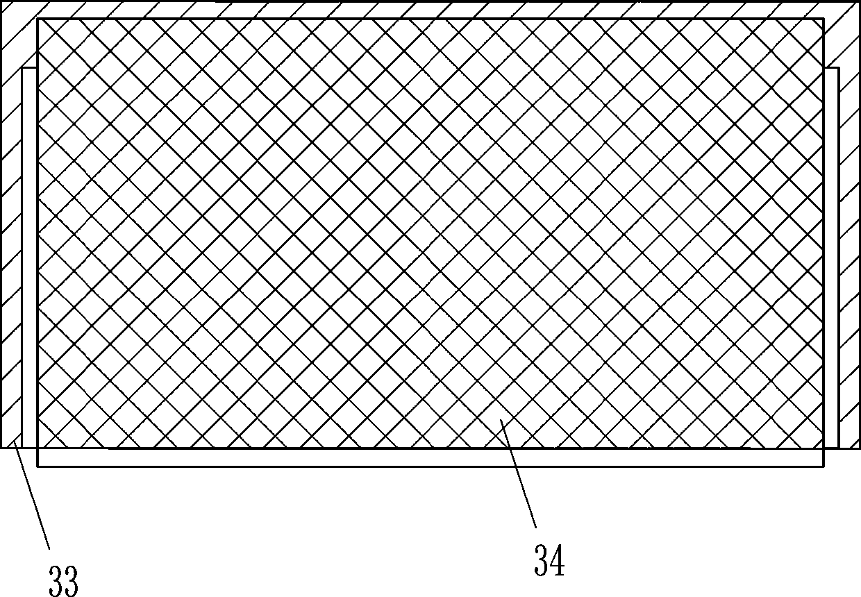
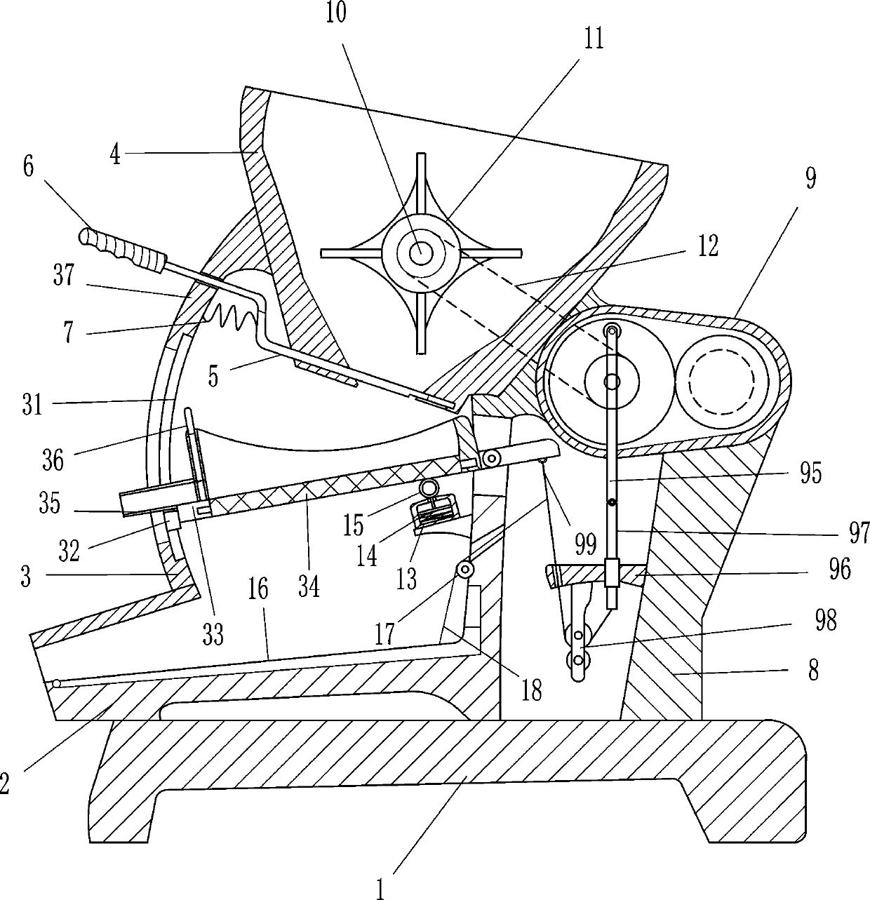
[0018] Such as Figure 1-3 As shown, a plastic particle raw material screening machine includes a support 1, a blanking box 2, a screening device 3, a blanking hopper 4, a baffle plate 5, a handle 6, a first elastic member 7, a bracket 8 and a driving device 9 , the top of the support 1 is provided with a blanking box 2 and a bracket 8 through bolt connection, the top of the blanking box 2 is provided with a screening device 3 for screening plastic granule raw materials, and the top of the screening device 3 is provided with a blanking hopper 4, the blanking hopper 4. A baffle plate 5 is movable at the discharge end, and a handle 6 is connected to the baffle plate 5. The handle 6 passes through the screening device 3, and a first elastic member 7 is arranged between the side wall of the screening device 3 and the material baffle plate 5. , the first elastic member 7 is a compression spring, and the top of the bracket 8 is provided with a driving device 9 capable of driving the...
Embodiment 2
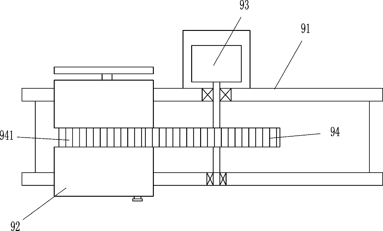
[0023] Such as Figure 1-3 Shown, on the basis of embodiment 1, also include rotating shaft 10, dispersing wheel 11 and conveying mechanism 12, be provided with rotating shaft 10 on the hopper 4, be provided with dispersing wheel 11 on the rotating shaft 10, rotating shaft 10 and the cylindrical drum 92 are connected by a transmission mechanism 12, and the transmission mechanism 12 is a belt drive. The rotating motor 93 works, which can drive the cylindrical drum 92 to work. The cylindrical drum 92 drives the rotating shaft 10 to rotate through the transmission mechanism 12, and then drives the dispersing wheel 11 to rotate, and then breaks up the plastic particle raw materials to facilitate subsequent sorting operations.
[0024] It also includes a sleeve 13, a second elastic member 14 and a top block 15. The side wall of the box body 37 is provided with a sleeve 13, and a second elastic member 14 is slidably arranged in the sleeve 13. The second elastic member 14 is a compre...
PUM
 Abstract
Description
Claims
Application Information