Ship shafting adjusting method
An adjustment method and shafting technology, applied to ships and other directions, can solve problems such as quality impact, accumulation of subtle errors, and ship construction errors, and achieve the effects of improving efficiency, reducing costs, and improving data accuracy
- Summary
- Abstract
- Description
- Claims
- Application Information
AI Technical Summary
Problems solved by technology
Method used
Image
Examples
Embodiment 1
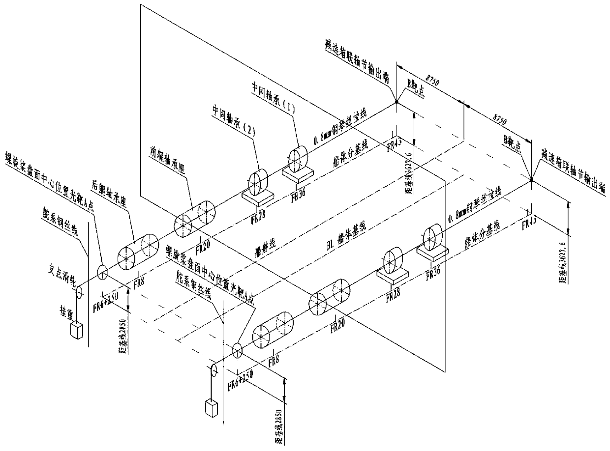
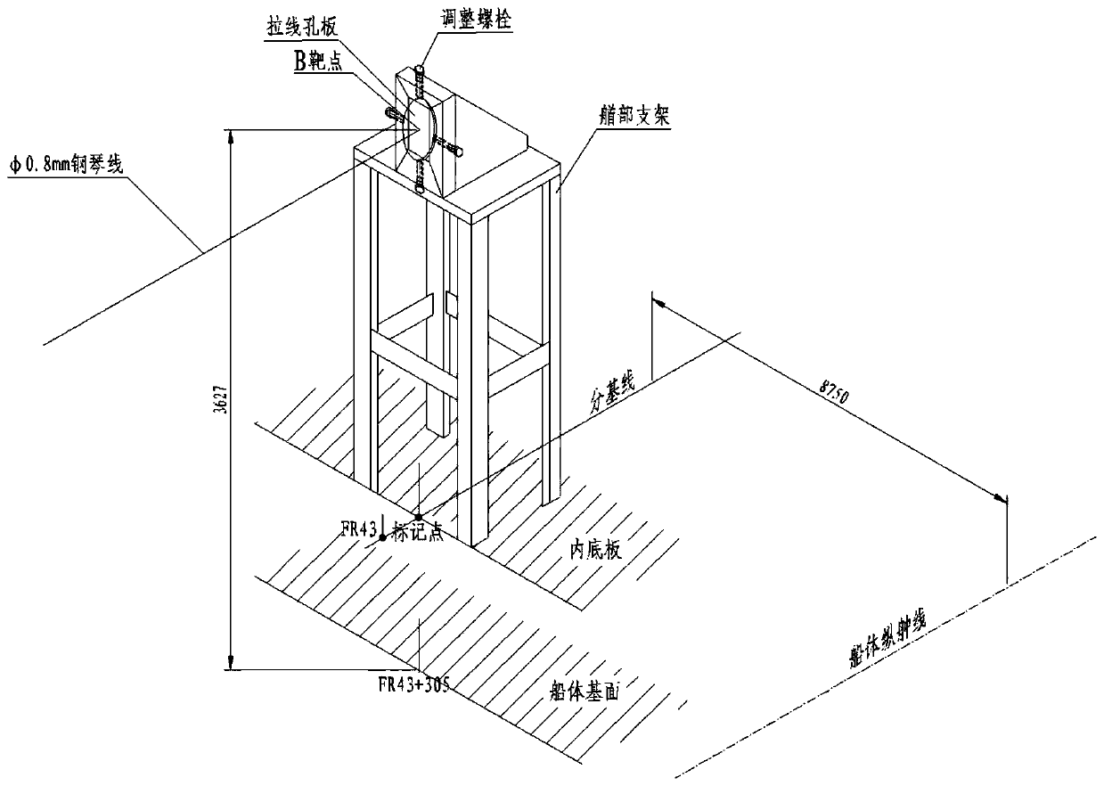
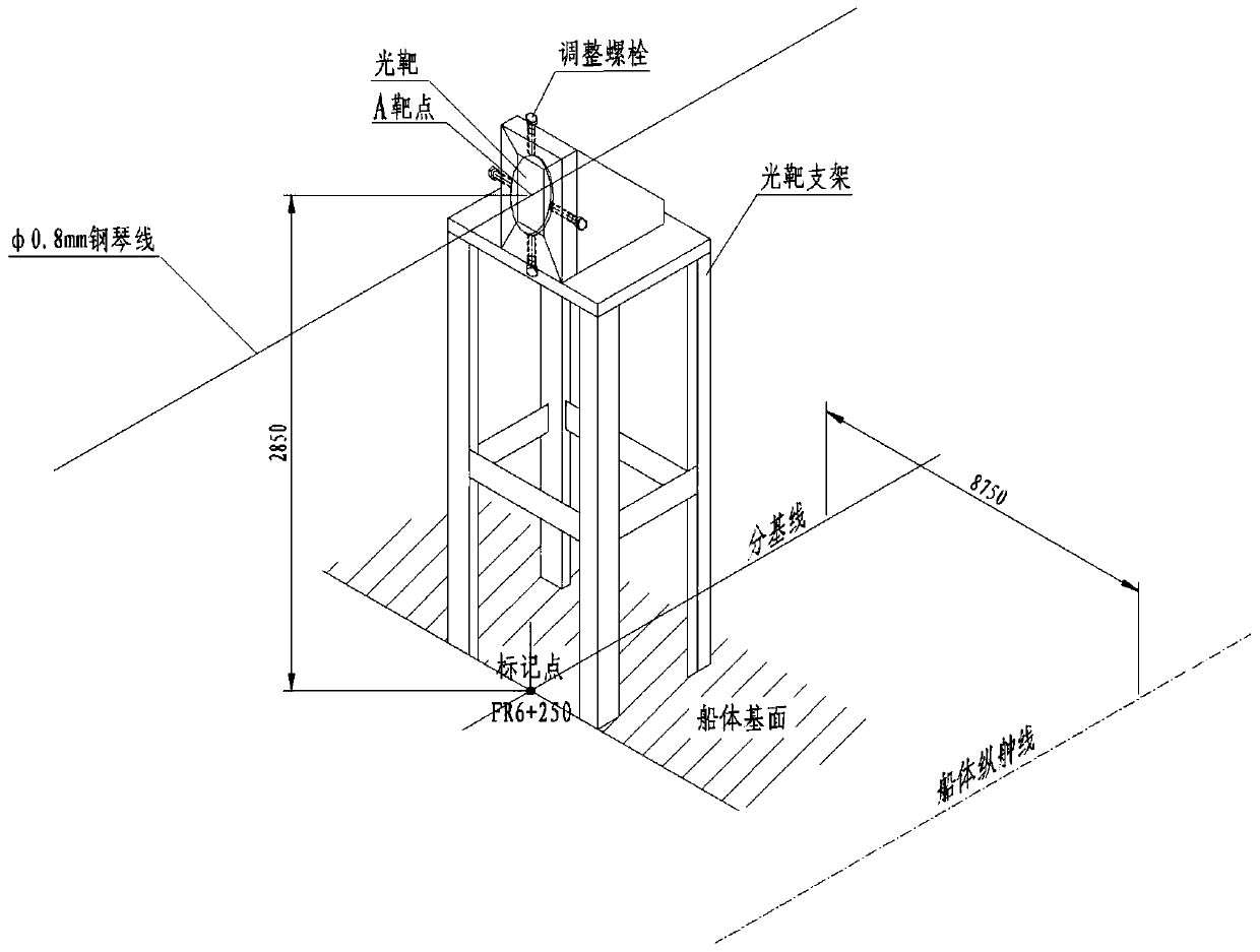
[0024] Such as Figure 1-3 As shown, in the embodiment of the present invention, the ship is a double-shaft system, and the shaft system is composed of a propeller shaft (stern shaft), a propeller (with a fixed draft tube), a hydraulic coupling, a reduction box, and the like. The center of the propeller disk is located at FR6+250mm, 2850mm away from the hull baseline and above its baseline; the output flange end of the gearbox is at the FR42+1144.8 rib position, 3627.6mm away from the hull baseline. The total length of the two-point shafting is 29.705m, the inclination angle of the shafting center line to the hull baseline is 1.5°, and the two axes are symmetrically arranged at a distance of 8750mm from the midship line.
[0025] Step 1. Determine the theoretical centerline of the shafting system
[0026] Firstly, the steel wire drawing method is used on the left and starboard sides to find out the bow and stern points that determine the theoretical center line of the shaftin...
PUM
| Property | Measurement | Unit |
|---|---|---|
| Diameter | aaaaa | aaaaa |
Abstract
Description
Claims
Application Information
 - R&D
- Intellectual Property
- Life Sciences
- Materials
- Tech Scout
- Unparalleled Data Quality
- Higher Quality Content
- 60% Fewer Hallucinations
Browse by: Latest US Patents, China's latest patents, Technical Efficacy Thesaurus, Application Domain, Technology Topic, Popular Technical Reports.
© 2025 PatSnap. All rights reserved.Legal|Privacy policy|Modern Slavery Act Transparency Statement|Sitemap|About US| Contact US: help@patsnap.com


