
Drainage device of washing machine

A technology for drainage devices and washing machines, applied in washing devices, other washing machines, textiles and papermaking, etc., can solve the problems of slow drainage speed, poor drainage effect, interference, etc., and achieve the effect of avoiding trapped air

Pending Publication Date: 2020-04-28
WHIRLPOOL CHINA
View PDF0 Cites 0 Cited by
  • Summary
  • Abstract
  • Description
  • Claims
  • Application Information

AI Technical Summary

Problems solved by technology

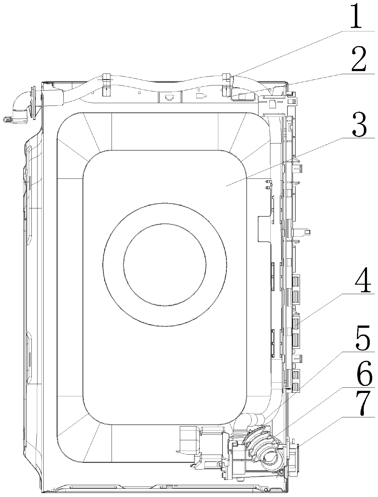
[0002] At present, the drainage principle of the upper drainage system of the existing drum washing machine is as follows: one end of the outer tub drainage pipe is connected to the outer tub, the other end is connected to the drainage pump, one end of the outer drainage pipe is connected to the drainage pump, and the other end is The side wall of the washing machine is fixed at the rear side of the box and the height is fixed at the position of 80cm. The drainage structure of the existing washing machine is uncertain due to the water outlet and the water inlet of the drainage pump, and because the drainage is too fast, the water flow makes the The gas gathers at the upper end of the drainage pump, causing the interference of trapped air, making the drainage effect poor and the drainage speed slow

Method used


Image

  • Drainage device of washing machine
  • Drainage device of washing machine
  • Drainage device of washing machine

Examples


Embodiment Construction

[0018] The following will clearly and completely describe the technical solutions in the embodiments of the present invention with reference to the accompanying drawings in the embodiments of the present invention. Obviously, the described embodiments are only some, not all, embodiments of the present invention.

[0019] Examples of the described embodiments are shown in the drawings, wherein like or similar reference numerals designate like or similar elements or elements having the same or similar functions throughout. The embodiments described below by referring to the figures are exemplary and are intended to explain the present invention and should not be construed as limiting the present invention.

[0020] In describing the present invention, it should be understood that the terms "center", "longitudinal", "transverse", "length", "width", "thickness", "upper", "lower", "front", " Back", "Left", "Right", "Vertical", "Horizontal", "Top", "Bottom", "Inner", "Outer", "Clock...


PUM


Abstract

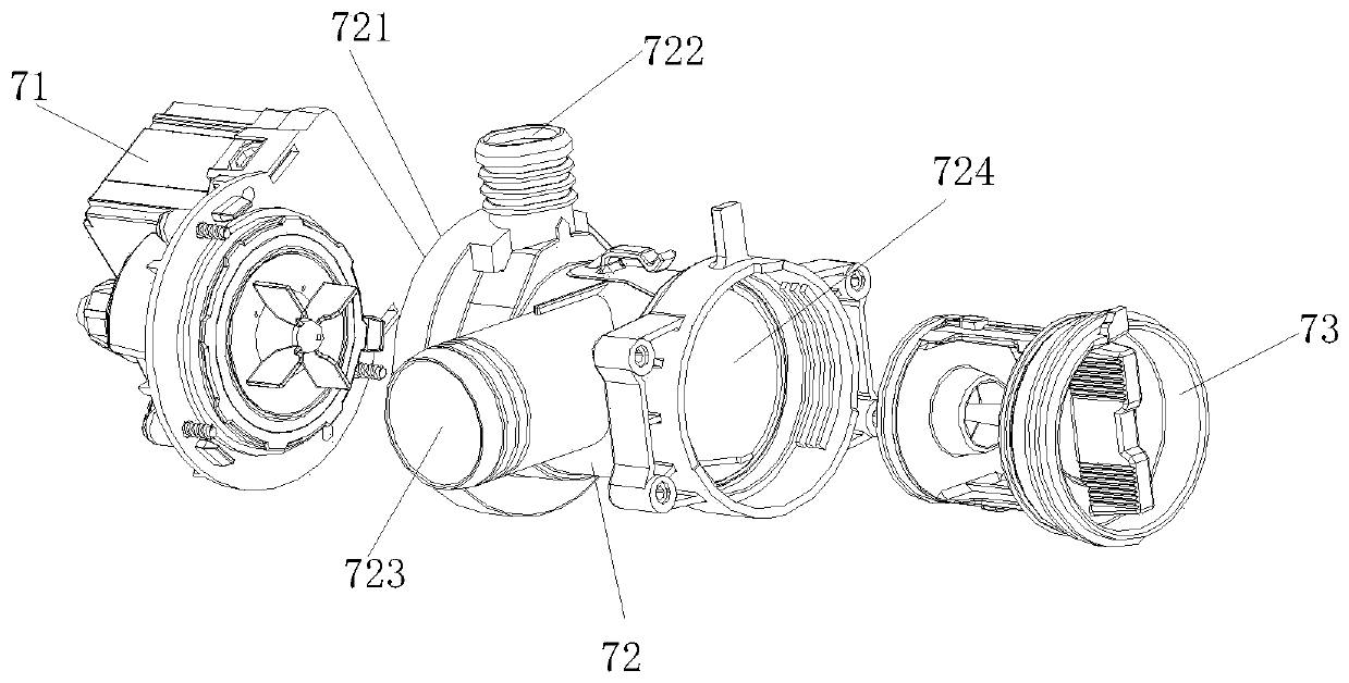
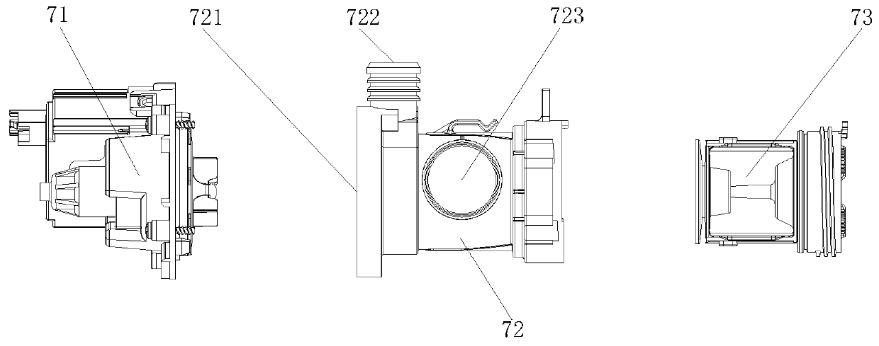
The invention discloses a drainage device of a washing machine. The drainage device comprises an outer washing machine box, a drainage pipe, a drainage inner pipe and a drainage pump assembly; the drainage pump assembly is arranged at the bottom of the outer washing machine box; the drainage pipe is arranged above the drainage pump assembly; the drainage pipe adopts an upper drainage installationmode; a water inlet pipeline of the drainage pipe is fixed to the outer washing machine box through a fixing frame; and a supporting plate is arranged at the upper part of the outer washing machine box. According to the drainage device of the washing machine in the invention, water is drained from the inside of the washing machine in an upper drainage mode, the water inlet pipeline of the drainagepipe feeds water vertically upwards, so that unsmooth water flow caused by air trapping in the drainage pump assembly is prevented; meanwhile, a filtering cavity is arranged in the drainage pump assembly, and water flows enter an impeller cavity through the filtering cavity to be drained away, so that sundries are prevented from blocking an impeller; and simultaneously, a water inlet of the drainage pump is arranged at the top of the filtering cavity, and the water flows enter the drainage pump assembly from the top, so that air trapping caused by air gathering at the top is prevented.

Description

technical field [0001] The invention relates to the technical field of washing machine production, in particular to a washing machine drainage device. Background technique [0002] At present, the drainage principle of the upper drainage system of the existing drum washing machine is as follows: one end of the outer tub drainage pipe is connected to the outer tub, the other end is connected to the drainage pump, one end of the outer drainage pipe is connected to the drainage pump, and the other end is The side wall of the washing machine is fixed at the rear side of the box and the height is fixed at the position of 80cm. The drainage structure of the existing washing machine is uncertain due to the water outlet and the water inlet of the drainage pump, and because the drainage is too fast, the water flow makes the The gas gathers at the upper end of the drainage pump, causing the interference of trapped air, making the drainage effect poor and the drainage speed slow. Con...

Claims


Application Information

Patent Timeline
Patent Type & Authority Applications(China)
IPC IPC(8): D06F39/08D06F39/10
CPCD06F39/085D06F39/10
Inventor 王浩贾蒙程长春
Owner WHIRLPOOL CHINA
Learn More