Assembled toilet floor drainage structure

A technology of drainage structure and toilet, applied in the field of bathroom

Active Publication Date: 2020-04-28
山西建投装饰产业有限公司 +2
View PDF5 Cites 3 Cited by
  • Summary
  • Abstract
  • Description
  • Claims
  • Application Information

AI Technical Summary

Problems solved by technology

[0002] With the rise of prefabricated building structures, bathrooms have gradually tried to adopt this method. Due to the use of more water in the bathroom, its drainage function is a part that people cannot ignore. For now, its drainage performance is relatively good. , but the vast majority ...

Method used


Image

  • Assembled toilet floor drainage structure
  • Assembled toilet floor drainage structure
  • Assembled toilet floor drainage structure

Examples


Embodiment Construction

[0016] In order to make the purpose, technical solutions and advantages of the embodiments of the present invention clearer, the technical solutions in the embodiments of the present invention will be clearly and completely described below in conjunction with the drawings in the embodiments of the present invention. Obviously, the described embodiments It is a part of embodiments of the present invention, but not all embodiments. Based on the embodiments of the present invention, all other embodiments obtained by persons of ordinary skill in the art without creative efforts fall within the protection scope of the present invention.

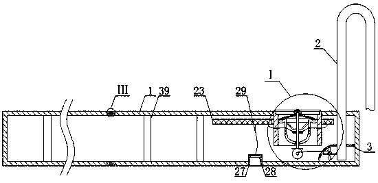
[0017]An assembled bathroom floor drainage structure, as shown in the figure, includes a water tank 1 that can be assembled. One end of the top surface of the water tank 1 is fixedly connected to one end of a U-shaped pipe 2. The opening of the U-shaped pipe 2 faces downward, and the U-shaped pipe 2 The other end of the U-shaped pipe 2 is connecte...


PUM

PropertyMeasurementUnit
Heightaaaaaaaaaa

Abstract

The invention discloses an assembled toilet floor drainage structure. The structure comprises an assembled water tank, wherein one side of the top surface of the water tank is fixedly connected with one end of a U-shaped pipe; a box body is fixedly installed in the water tank; one end of the U-shaped pipe penetrates through the water tank and the box body and is positioned at the inner bottom of the box body; a plurality of blades are fixedly installed on the periphery of a first rotating shaft; a line wheel is fixedly installed on the periphery of the first rotating shaft; the periphery of the line wheel is fixedly connected with one end of a first line rope; a first line hole and a water inlet groove are formed on the inner side of the box body; the top surface of the inner wall of the water tank is fixedly connected with the upper end of a sleeve; the top of the inner wall of the sleeve is provided with a circle of groove; and a grid plate is movably arranged in the groove. The assembled toilet floor drainage structure is particularly suitable for use in an apartment house, waste water is effectively utilized, and resources are saved; two layers of water seals are arranged between an underground drain pipe and a toilet, thus peculiar smell can be effectively prevented from being emitted into the toilet; and a scraper can rotate several circles during each time of toilet flushing by arranging the U-shaped pipe and other structures, and the technical effect of automatically removing attachments on the top of the grid plate can be achieved.

Description

technical field [0001] The invention belongs to the field of sanitary ware, in particular to an assembled toilet ground drainage structure. Background technique [0002] With the rise of prefabricated building structures, toilets have also begun to gradually try to adopt this method. Due to the use of more water in the toilet, its drainage function is a part that people cannot ignore. For now, its drainage performance is relatively good. , but the vast majority of bathing wastewater is directly discharged, and it cannot be collected and reused. From this perspective, if the prefabricated toilet structure can be effectively combined with wastewater storage, water resources will be saved. Therefore, we A prefabricated bathroom floor drainage structure is proposed. Contents of the invention [0003] The invention provides an assembled toilet ground drainage structure to solve the defects in the prior art. [0004] The present invention is achieved through the following tech...

Claims


Application Information

Patent Timeline
IPC IPC(8): E03F5/10E03F5/14E03F5/20E03F7/00E03B1/04
CPCE03B1/041E03B2001/045E03F5/10E03F5/107E03F5/14E03F5/20E03F7/00
Inventor 刘志强张乃胜黄强
Owner 山西建投装饰产业有限公司
Why Eureka
Try Eureka