Kite electricity generating method capable of transmitting torque through mooring rope
A technology for transmitting torque and kites, which is used in wind power generation, wind turbines at right angles to the wind direction, and hydropower generation. Difficult and fragile effects
- Summary
- Abstract
- Description
- Claims
- Application Information
AI Technical Summary
Problems solved by technology
Method used
Image
Examples
Embodiment 1
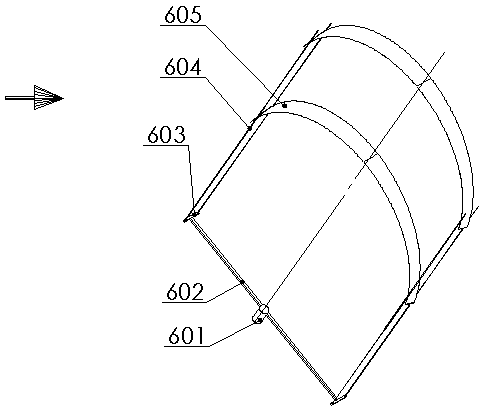
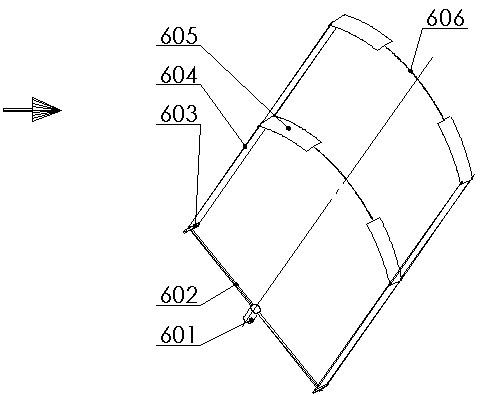
[0025] Embodiment 1: as figure 1 As shown, a kite generator in the form of a windmill for torque transmission by cables includes a main shaft (601), a rotating arm (602), a small arm (603), a cable (604), and a parafoil (605). The main shaft (601) is radially connected with two rotating arms (602) evenly distributed along the axis, the rotating arm (602) is vertically connected with the forearm (603), and the forearm (603) passes through two cables (604) Connected to the parafoil (605), the two ends of the parafoil (605) are connected to the two ends of the two forearms (603) with 2 cables (604) respectively. Adjust the relative lengths of the four cables (604), so that the parafoil (605) forms a flexible propeller and rotates in the wind. The cables (604) drive the main shaft (601) to rotate, and the main shaft (601) is connected to a generator or other work mechanical.
[0026] When starting up, the parafoils on both sides of the main shaft are the same as the wings on bo...
Embodiment 2
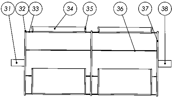
[0028] Embodiment 2: as image 3 As shown, a kite generator in the form of a waterwheel for torque transmission by cables includes a drive shaft (31), a drive rod (32), a transmission rope (33), a cloth sail (34), a cloth sail mast (35), a limit Bit rope (36), driven lever (37), driven shaft (38). One end of the driving shaft (31) is connected to the middle of the driving rod (32), and the two ends of the driving rod (32) are connected with two transmission ropes (33), and the transmission rope (33) is connected with cloth sails (34), cloth sails (34 ) is threaded with a reinforced cloth sail mast (35), the other end of the transmission rope (33) is connected to one end of the driven rod (37), and the middle of the driven rod (37) is connected to the driven shaft (38). Axle (38) is generator shaft, and one end of limit rope (36) is connected to driving rod (32), and the other end is connected to driven rod (37).
[0029] image 3 The position shown is that the generator is ...
Embodiment 3
[0031] Example 3: Figure 4 It is a kite power generation method in which cables in the form of kite strings transmit torque. Figure 5 yes Figure 4 Partial enlarged view at A in the center, such as Figure 4 Shown is a kite power generation method in which cables transmit torque in the form of a kite string, including a main shaft (101), a boom (102), a small arm (103), and a kite string (104). The main shaft (101) is connected to a generator or a motivation. At least two large arms (102) are connected to the main shaft, a stopper (105) is arranged at the end of the large arm (102), and the small arm (103) is connected to the large arm (102) through a hinge. A kite string (104) is connected to both ends respectively, and the position of the hinge on the forearm (103) is not at the midpoint of the forearm (if the position of the hinge on the forearm (103) is the midpoint, then the same The length or size of the two kite strings on the forearm should be different), the hin...
PUM
 Abstract
Description
Claims
Application Information
 - R&D Engineer
- R&D Manager
- IP Professional
- Industry Leading Data Capabilities
- Powerful AI technology
- Patent DNA Extraction
Browse by: Latest US Patents, China's latest patents, Technical Efficacy Thesaurus, Application Domain, Technology Topic, Popular Technical Reports.
© 2024 PatSnap. All rights reserved.Legal|Privacy policy|Modern Slavery Act Transparency Statement|Sitemap|About US| Contact US: help@patsnap.com


