
self-excited brake calipers

一种制动钳、自激的技术,应用在制动器、制动构件、制动器类型等方向,能够解决制造成本高、量产性低、结构复杂等问题,达到增加强化效果的效果

Active Publication Date: 2021-06-11
KYUNG CHANG IND +1
View PDF18 Cites 0 Cited by
  • Summary
  • Abstract
  • Description
  • Claims
  • Application Information

AI Technical Summary

Problems solved by technology

[0003] However, the existing self-excited brakes are complex in structure, low in mass production and high in manufacturing cost. In the structure using wedges, self-locking (self-locking) due to insertion phenomenon and other reasons are self-defeating. Excitation brakes are not practical for the vehicle

Method used


Image

  • self-excited brake calipers
  • self-excited brake calipers
  • self-excited brake calipers

Examples


Embodiment Construction

[0032] Hereinafter, the present invention will be specifically described with reference to the drawings.

[0033] In this specification, only the essential components necessary for the description of the present invention are described, and the components irrelevant to the essence of the present invention are not mentioned. And, it should be interpreted in a non-exclusive sense including other constituent elements, not in a sense including only the mentioned exclusive constituent elements.

[0034] In this specification, inboard refers to the vehicle side of the brake disc, and outboard refers to the vehicle's outer side of the brake disc.

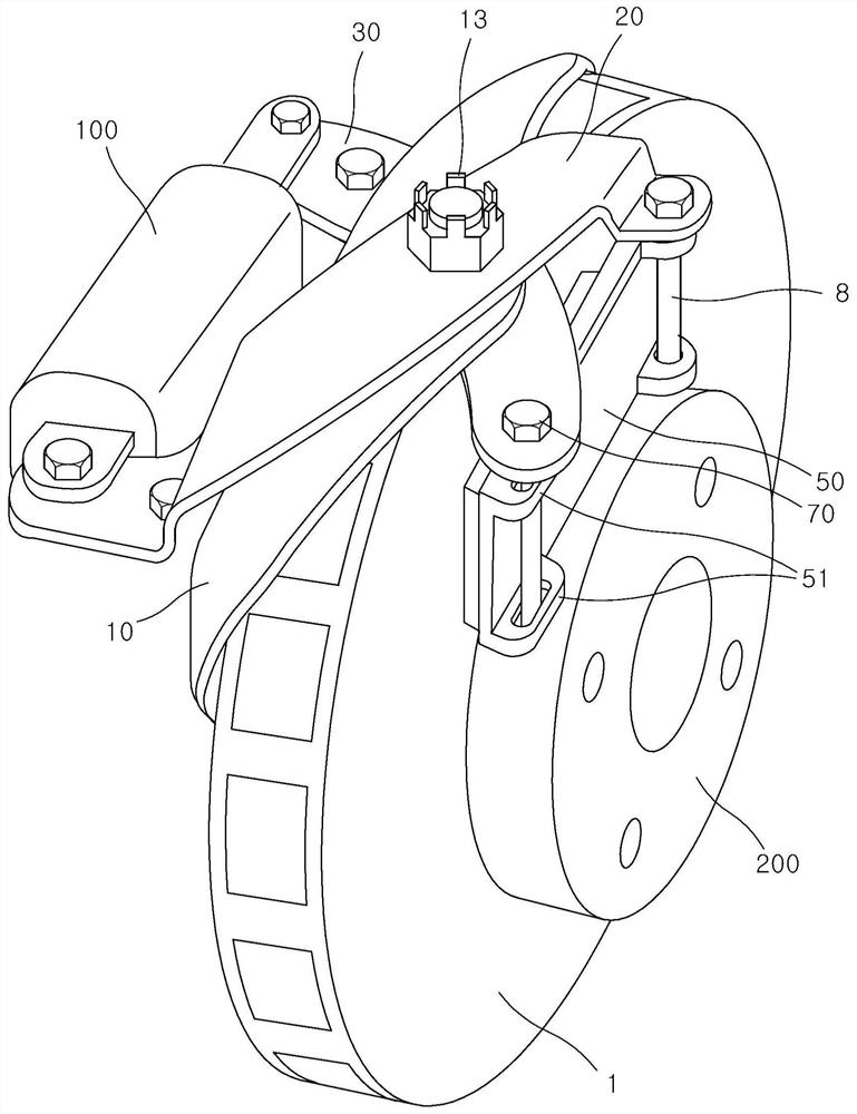
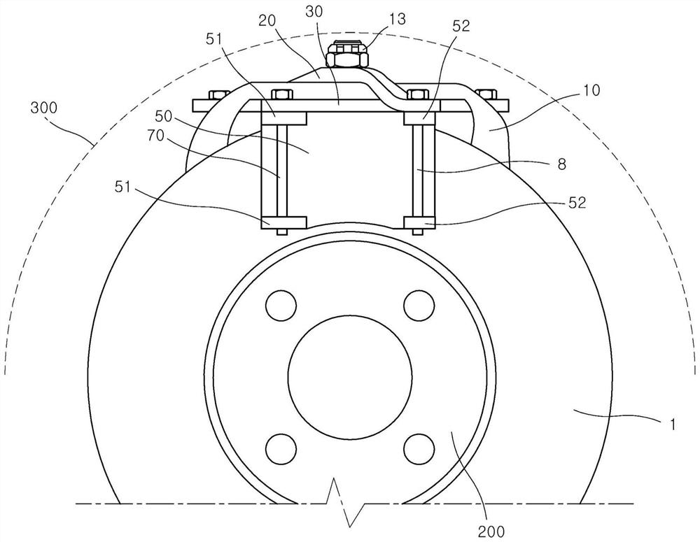
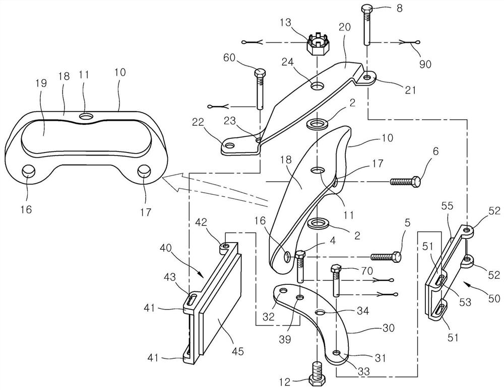
[0035] figure 1 It is a perspective view of a brake disc with a self-excited brake caliper installed in the present invention, figure 2 is a plan view viewed from the outside direction, image 3 It is an exploded perspective view of the self-excited brake caliper of the present invention.

[0036] The self-excited brake caliper of the...


PUM


Abstract

The present invention relates to self-exciting brake calipers. The self-excited brake caliper of the present invention comprises: a caliper bracket (10), which is fixed to the vehicle frame and includes a rotating shaft extending to the height direction of the vehicle; the first caliper arm (20) and the second caliper arm (30), which can Rotating with respect to the axis of rotation (12) of the caliper bracket (10) and connected in a crosswise manner; the inner brake plate (40); the outer brake plate (50). The first caliper arm (20; upper arm) is connected to the first end (41) of the inner brake plate (40) in a sliding manner on the inner side of the brake disc, and the outer end (21) of the first caliper arm (20) Fixedly connected to the second end (52) of the outboard brake plate (50). The second caliper arm (30; lower arm) is fixedly connected to the second end (42) of the inner brake plate (40) on the inner side of the brake disc, the outer end (31) of the second caliper arm (30) can be slid The way is connected with the first end (51) of the outer brake plate (50). The inner ends (22, 32) of the first (20) and second (30) tong arms are provided so as to receive the transmitted drive force of the drive means.

Description

technical field [0001] The invention relates to a self-energizing brake caliper. Background technique [0002] In a hydraulic brake system, when a driver steps on a brake pedal, pressure generated in a master cylinder is converted into braking force by a disc brake caliper or a drum brake wheel cylinder. A self-energizing brake is included as a device to enhance the braking force, for example, a self-energizing brake utilizing a ball or a ramp disclosed in U.S. Patent No. 5,012,901, U.S. Patent No. 6 , No. 318, No. 513 discloses a self-excited brake utilizing the wedge effect (wedge effect). [0003] However, the existing self-excited brakes are complex in structure, low in mass production and high in manufacturing cost. In the structure using wedges, self-locking (self-locking) due to insertion phenomenon and other reasons are self-defeating. Brakes are not actually applicable to the vehicle. [0004] In addition, in Brake-by-wire (Brake-by-wire), when using an EMB (elec...

Claims


Application Information

Patent Timeline
Patent Type & Authority Patents(China)
IPC IPC(8): F16D55/2255F16D65/092F16D65/18F16D125/70
CPCF16D55/2255F16D65/18F16D65/092F16D2055/002F16D2055/0008F16D2125/70F16D55/2245F16D65/0075F16D65/095F16D2125/64F16D2125/60F16D2121/04F16D2121/24F16D51/50F16D2055/0029B60T1/065F16D65/0056F16D2125/68
Inventor 李光镇
Owner KYUNG CHANG IND
Learn More