Electromagnetic heating flanging mold

A flanging mold, electromagnetic technology, applied in the direction of forming tools, manufacturing tools, metal processing equipment, etc., can solve the problems of low heating efficiency, high temperature at the production site, long preheating time, etc., and achieve the effect of high heat conversion efficiency

Pending Publication Date: 2020-05-01
天津航天长征技术装备有限公司
View PDF0 Cites 1 Cited by
  • Summary
  • Abstract
  • Description
  • Claims
  • Application Information

AI Technical Summary

Problems solved by technology

[0002] There are two types of flanging products: hot flanging and cold flanging. The traditional heating method of hot flanging is resistance wire heating or electric furnace heating

Method used


Image

  • Electromagnetic heating flanging mold

Examples


Embodiment 1

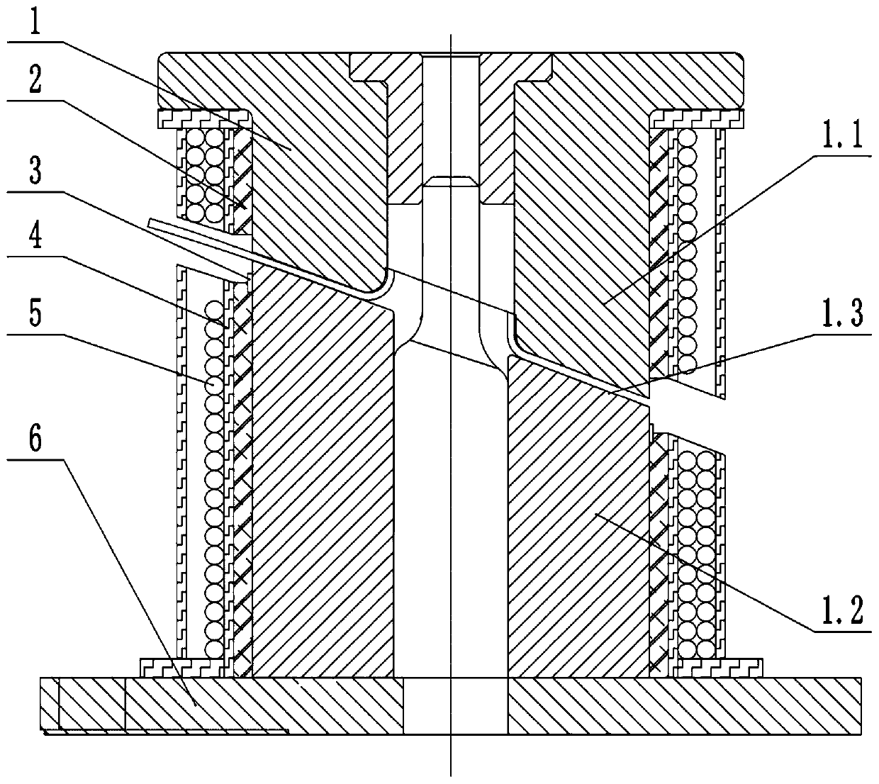
[0022] An electromagnetic heating flanging mold, comprising a mold main body 1, glass fiber cotton 2, fiber hard board 4 and high temperature resistant wire 5, the mold main body 1 is divided into an upper mold 1.1 on the upper part and a lower mold 1.2 on the lower part, and the outside of the mold main body 1 Wrap the glass fiber cotton 2 for heat insulation. The outside of the glass fiber cotton 2 is provided with a heat-resistant fiber hard board 4 that plays a supporting role. The fiber hard board 4 provides attachment for the heat-resistant high-temperature wire 5 . Winding high temperature resistant wire 5 coils, high temperature resistant wire 5 is mica wire, working temperature is 1000°C, upper mold 1.1 and lower mold 1.2 respectively wind a high temperature resistant wire 5, upper mold 1.1 winds high temperature resistant wire 5 and lower mold 1.2 The high-temperature-resistant electric wire 5 wound on the top is connected in series to the power supply, and two temper...

Embodiment 2

[0029] An electromagnetic heating flanging mold, comprising a mold main body 1, glass fiber cotton 2, fiber hard board 4 and high temperature resistant wire 5, the mold main body 1 is divided into an upper mold 1.1 on the upper part and a lower mold 1.2 on the lower part, and the outside of the mold main body 1 Wrap the glass fiber cotton 2 for heat insulation. The outside of the glass fiber cotton 2 is provided with a heat-resistant fiber hard board 4 that plays a supporting role. The fiber hard board 4 provides attachment for the heat-resistant high-temperature wire 5 . Winding high temperature resistant wire 5 coils, high temperature resistant wire 5 is mica wire, working temperature is 1000°C, upper mold 1.1 and lower mold 1.2 respectively wind a high temperature resistant wire 5, upper mold 1.1 winds high temperature resistant wire 5 and lower mold 1.2 The high-temperature-resistant electric wire 5 wound on the top is connected in series to the power supply, and two temper...


PUM


Abstract

An electromagnetic heating flanging mold comprises a mold body, glass fiber cotton, a fiber hard plate and high-temperature-resistant electric wires. The mold body is divided into an upper mold on theupper portion and a lower mold on the lower portion. The outer side of the mold body is wrapped by the glass fiber cotton achieving a thermal insulation effect. The heat-resistant fiber hard plate achieving a supporting effect is arranged outside the glass fiber cotton. A high-temperature-resistant electric wire coil is wound in the fiber hard plate. The high-temperature-resistant electric wiresare wound on the upper mold and the lower mold correspondingly. The high-temperature-resistant electric wire wound on the upper mold and the high-temperature-resistant electric wire wound on the lowermold are connected to a power supply after being connected in series. Two temperature sensors are arranged on the periphery of the face, connected with the upper mold in a butt joint manner, of the lower mold. The two temperature sensors are connected to a temperature controller outside the mold body. The problem that due to the adoption of resistance type heating of electric heating sheets, electric heating coils and the like and the adoption of the heat conduction type heating, the thermal efficiency is low is fundamentally solved through the manner of electromagnetic heating, product self-heating and direct heating with the high thermal conversion efficiency capable of reaching up to 95%

Description

technical field [0001] The invention relates to a mold, in particular to an electromagnetic heating flanging mold. Background technique [0002] There are two types of flanging products: hot flanging and cold flanging. The traditional heating method of hot flanging is resistance wire heating or electric furnace heating. The heat conduction heating method has low heating efficiency, short service life, and high production site temperature during heating. , long warm-up time and other shortcomings. Contents of the invention [0003] In order to solve the above problems, the present invention provides an electromagnetic heating flanging mold with controllable heating temperature and high thermal efficiency. [0004] The technical scheme that the present invention takes: [0005] An electromagnetic heating flanging mold, including a mold body, glass fiber cotton, fiber hard board and high temperature resistant wires, the mold body is divided into an upper mold and a lower mo...

Claims


Application Information

Patent Timeline
IPC IPC(8): B21D19/08B21D37/16
CPCB21D19/08B21D37/16
Inventor 倪江涛朱增起简宏韬田兴陶现宾李继光毕海娟张下陆田恕
Owner 天津航天长征技术装备有限公司
Why Eureka
Try Eureka