
Feeding structure for sludge treatment tank

A technology for sludge treatment and feeding, which is applied in sludge treatment, water/sludge/sewage treatment, chemical instruments and methods, etc., and can solve the problems of low sludge transmission efficiency and other issues

Pending Publication Date: 2020-05-01
西安金清泰环境科技有限公司
View PDF0 Cites 0 Cited by
  • Summary
  • Abstract
  • Description
  • Claims
  • Application Information

AI Technical Summary

Problems solved by technology

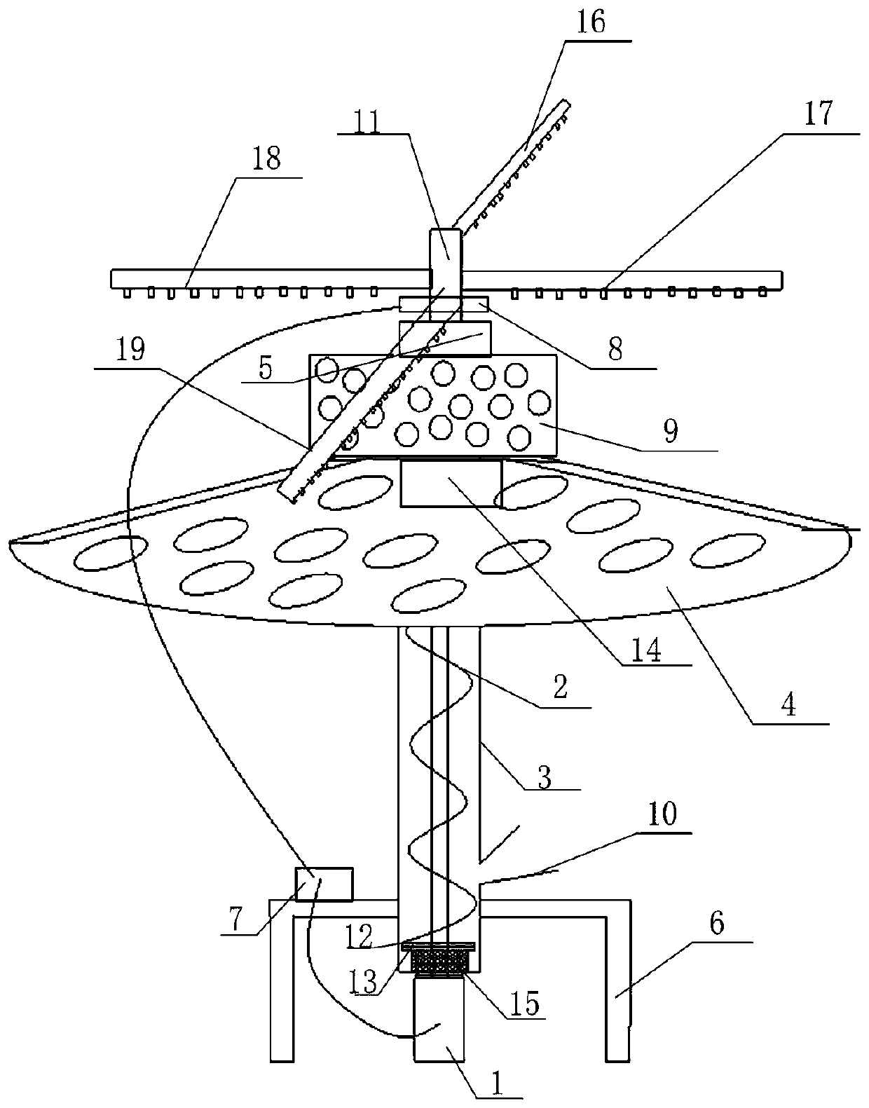
[0004] In order to solve the problem of low efficiency of conveying sludge by conveyor belts in the prior art, the embodiment of the present invention provides a feeding structure for sludge treatment tanks

Method used


Image

  • Feeding structure for sludge treatment tank

Examples


Embodiment Construction

[0023] The technical solutions in the embodiments of the present invention will be described below with reference to the drawings in the embodiments of the present invention.

[0024] It should be noted that the feeding structure for the sludge treatment tank provided by the embodiment of the present invention can be used in the field of sludge treatment equipment.

[0025] In order to solve the problem of low transfer efficiency of sludge conveyed by a conveyor belt in the prior art, an embodiment of the present invention provides a feeding structure for a sludge treatment tank. The specific technical scheme is as follows:

[0026] See figure 1 , the embodiment of the present invention provides a feeding structure for sludge treatment tanks, including: rotating motor 1, screw dragon 2, feeding shell 3, feeding tray 4, water storage tank 5, water outlet, drain pipe 11 , booster pump 8, discharge structure 9, feed port 10;

[0027] The working end of the rotating motor 1 is ...


PUM


Abstract

The embodiment of the invention provides a feeding structure for a sludge treatment tank. According to the feeding structure for the sludge treatment tank, sludge is conveyed from bottom to top through a spiral auger, in the conveying process, the sludge falling probability is greatly reduced, the conveying efficiency is improved, energy is saved, and the problem that in the prior art, the conveying efficiency is low due to the fact that a conveying belt is adopted for conveying sludge is solved.

Description

technical field [0001] The invention relates to the technical field of sludge treatment equipment, in particular to a feeding structure for a sludge treatment tank. Background technique [0002] At present, with the overall development of my country's economic and social undertakings, the country's requirements for environmental protection are also increasing, and the number of urban sewage treatment plants is also increasing. According to incomplete statistics, the residual products of sewage treatment in sewage treatment plants nationwide , only about 10% of the sludge is recycled to the land after being treated by composting and other technologies, about 20% is landfilled, and a smaller amount is used for incineration and construction materials utilization, etc. The living environment and social development environment bring serious secondary pollution. [0003] After decades of development in foreign developed countries, the sludge treatment and disposal technology has be...

Claims


Application Information

Patent Timeline
IPC IPC(8): C02F11/00
CPCC02F11/00
Inventor 陈穗君
Owner 西安金清泰环境科技有限公司
Learn More