Eureka AIR delivers breakthrough ideas for toughest innovation challenges, trusted by R&D personnel around the world.

Sampling device

A technology of sampling device and shaft installation, which is applied in the direction of sampling device, etc., to avoid various unpleasant smells, maintain the original tissue properties, avoid artificial freezing and thawing damage and waste samples

Pending Publication Date: 2020-05-01
SHANGHAI LIGOU SENSOR SCI & TECH
View PDF0 Cites 1 Cited by
  • Summary
  • Abstract
  • Description
  • Claims
  • Application Information

AI Technical Summary

Problems solved by technology

For biological samples of lesions such as tumors, it is necessary to take the tissue of the lesion center to the greatest extent during the research. If the traditional methods are used in the past, all the above problems cannot be solved.

Method used


Image

  • Sampling device
  • Sampling device
  • Sampling device

Examples


Embodiment 1

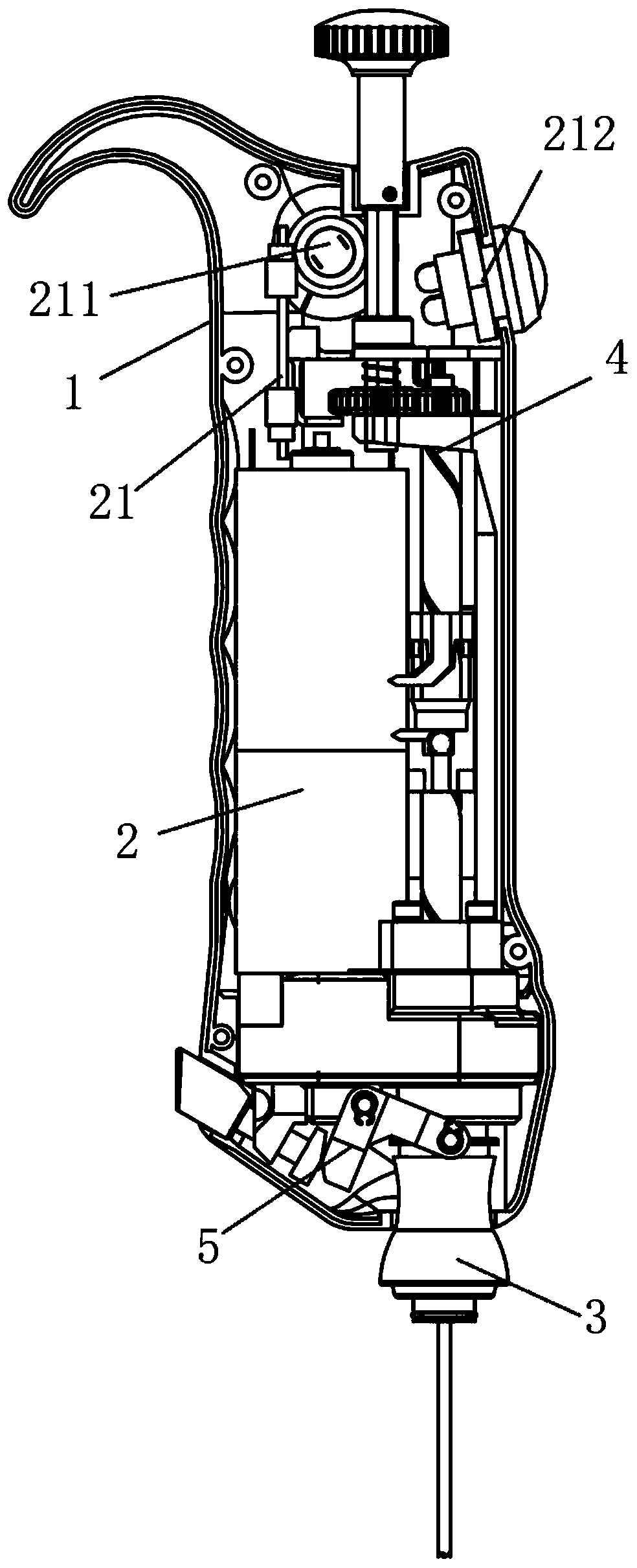
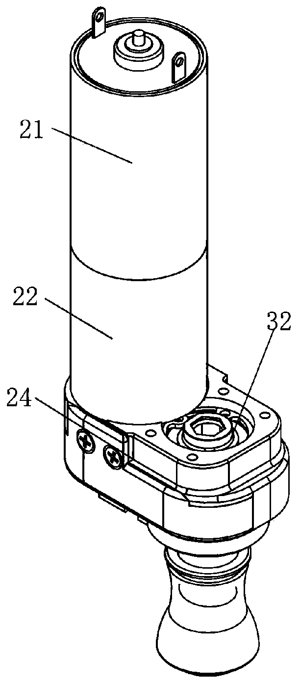
[0027] Such as Figure 1 to Figure 8 As shown, a sampling device includes a housing 1 in which a drive assembly 2, a drill bit assembly 3, and a material ejection assembly 4 are provided. The drill bit assembly includes a drill needle 31 and a drill needle installation A shaft 32, the drill pin mounting shaft is connected to the drive assembly and can drive the drill pin to rotate under the drive of the drive assembly. The withdrawal assembly includes a knob 41 and a withdrawal screw 42. The withdrawal screw is connected to the The drill bit assembly is connected, and the knob 41 is connected with the material withdrawal screw rod and can drive the material withdrawal screw rod to rotate for material withdrawal.

[0028] In this embodiment, the return assembly includes a mounting bracket 40, the mounting bracket is fixed in the housing, a cover plate 401 is arranged above the mounting bracket, the knob is arranged above the cover plate, and the cover plate is arranged There is a...

Embodiment 2

[0038] Such as Figure 1 to Figure 8 As shown, a sampling device includes a housing 1 in which a drive assembly 2, a drill needle assembly 3, and a material ejection assembly 4 are provided. The drill needle assembly includes a drill needle 31 and a drill needle installation A shaft 32, the drill pin mounting shaft is connected to the drive assembly and can drive the drill pin to rotate under the drive of the drive assembly. The withdrawal assembly includes a knob 41 and a withdrawal screw 42. The withdrawal screw is connected to the The drill bit assembly is connected, and the knob 41 is connected with the material withdrawal screw rod and can drive the material withdrawal screw rod to rotate for material withdrawal.

[0039] In this embodiment, the return assembly includes a mounting bracket 40, the mounting bracket is fixed in the housing, a cover plate 401 is arranged above the mounting bracket, the knob is arranged above the cover plate, and the cover plate is arranged Ther...


PUM


Abstract

The invention discloses a sampling device, which comprises a shell, wherein a drive assembly, a drill pin assembly and a discharge assembly are arranged in the shell; the drill pin assembly comprisesa drill pin and a drill pin mounting shaft; the drill pin mounting shaft is connected with the drive assembly and can drive the drill pin to rotate under the drive of the drive assembly; the dischargeassembly comprises a knob and a discharge screw rod; the discharge screw rod is connected with the drill pin assembly; the knob is connected with the discharge screw rod and can drive the discharge screw rod to rotate to discharge materials; and an experimenter operates the sampling device with one hand, clamps a to-be-sampled mother sample on a special freezing table, clamps a special limiting sleeve on a sampling test tube, starts a button and presses the sampling device to carry out sampling work. The sampling work is completed when the sampling quantity meets the original set quantity, and the sampled sample is spun out into a target container. The frozen sample is quantitatively taken out in a targeted manner on the premise of keeping the mother sample in a non-frozen-thawed state, and the original tissue property of an experimental sample is kept to the maximum extent.

Description

Technical field [0001] The invention relates to the field of sampling devices, in particular to a sampling device. Background technique [0002] At the current stage, the biological sample library adopts relatively simple and primitive methods for sampling various types of frozen samples. In a frozen state such as -196° or -80°, biological samples will become extremely hard. If some samples need to be taken out for experiments, usually the researcher will freeze and thaw the mother samples, and then knock the mother samples with the tip of tweezers or a knife Surface, make the surface cracks and even a small sample block collapse, pick out the small sample block into the target container for the next scientific research experiment. [0003] However, repeated freezing and thawing can cause a great loss of RNA in biological samples. Some brain tissue proteins may be lost or degraded after freezing and thawing, which will directly affect the results of medical research. Some samples...

Claims


Application Information

Patent Timeline
Patent Type & Authority Applications(China)
IPC IPC(8): G01N1/08
CPCG01N1/08
Inventor 戴蒙唐华英朱晓喆
Owner SHANGHAI LIGOU SENSOR SCI & TECH
Why Eureka
Eureka Blog
Learn More