

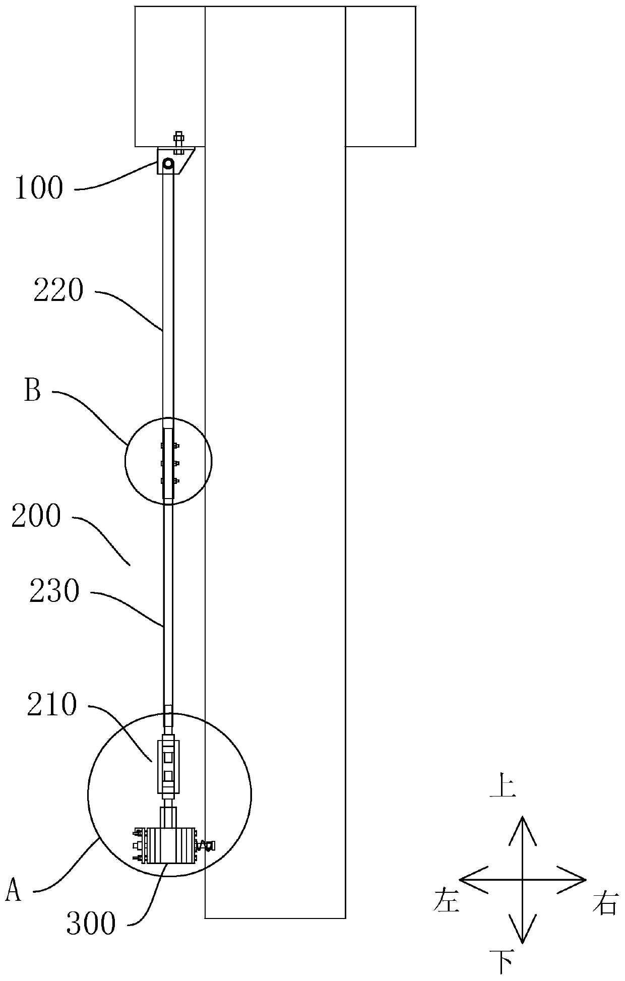
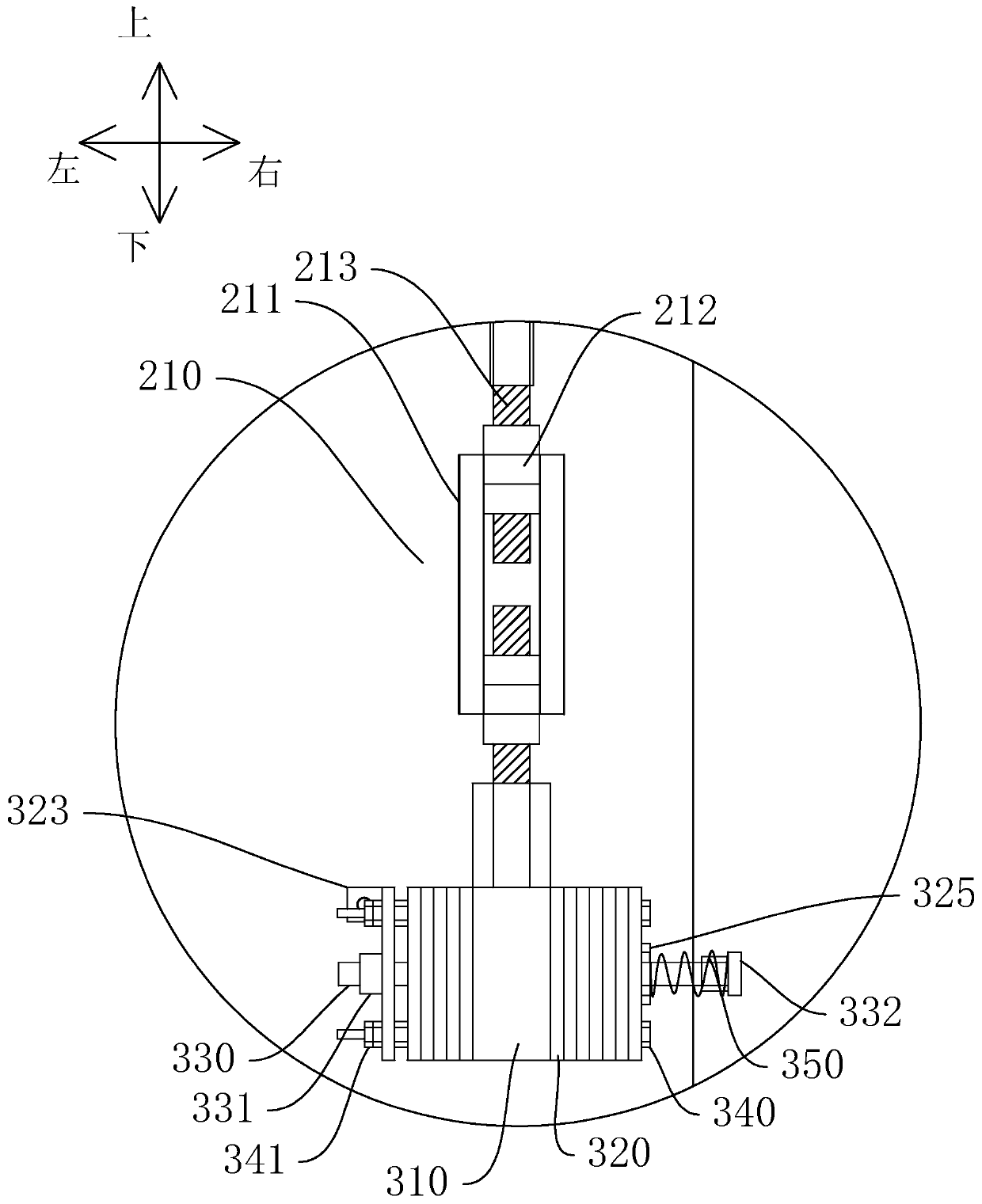
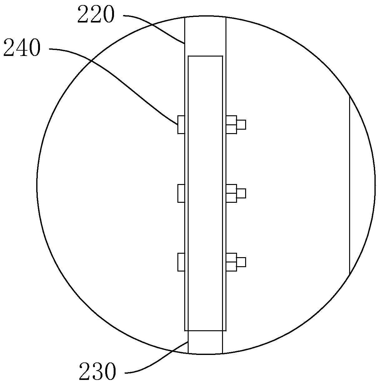
Impact pendulum bob device
An impact pendulum and mounting hole technology, applied in the field of impact pendulum devices, can solve the problems of difficult control of impact parameters, small adjustment degree of swing arm length, large fluctuation of test data, etc., to achieve free adjustment, impact stiffness, and Adjustment effect
- Summary
- Abstract
- Description
- Claims
- Application Information
AI Technical Summary
Problems solved by technology
Method used
Image

Examples
Embodiment Construction
[0024] This part will describe the specific embodiments of the present invention in detail, and the preferred embodiments of the present invention are shown in the accompanying drawings. Each technical feature and overall technical solution of the invention should not be construed as limiting the protection scope of the invention.
[0025] In the description of the present invention, it should be understood that the azimuth description, such as the azimuth or position relationship indicated by up, down, front, rear, left, right, etc., is based on the azimuth or position relationship shown in the drawings, only In order to facilitate the description of the present invention and simplify the description, it is not indicated or implied that the indicated device or element must have a particular orientation, be constructed and operated in a particular orientation, and therefore should not be construed as limiting the present invention.
[0026] In the description of the present in...
PUM
 Abstract
Description
Claims
Application Information