
Transconductance variable circuit and it variable bandwidth filter and gain amplifier

A variable and circuit technology, applied in adjustable filters, amplifiers, gated amplifiers, etc., can solve problems such as complex structure and reduced stability of equalizers

Inactive Publication Date: 2003-06-04
SAMSUNG ELECTRONICS CO LTD
View PDF1 Cites 0 Cited by
  • Summary
  • Abstract
  • Description
  • Claims
  • Application Information

AI Technical Summary

Problems solved by technology

However, if each frequency characteristic corresponding to the type of disc used in the optical disc reproducing apparatus and the type of pickup is set with an additional filter, if a filter is selectively used as required, the structure of the equalizer complex and its stability is reduced

Method used


Image

  • Transconductance variable circuit and it variable bandwidth filter and gain amplifier
  • Transconductance variable circuit and it variable bandwidth filter and gain amplifier
  • Transconductance variable circuit and it variable bandwidth filter and gain amplifier

Examples


Embodiment Construction

[0019] In the following description, many specific components, such as circuit structures, components, etc., are listed to provide a more complete understanding of the present invention. It will be apparent, however, to one skilled in the art that the present invention may be practiced without these specific details. Also, detailed descriptions of well-known features and constructions are omitted in order to more clearly describe the present invention.

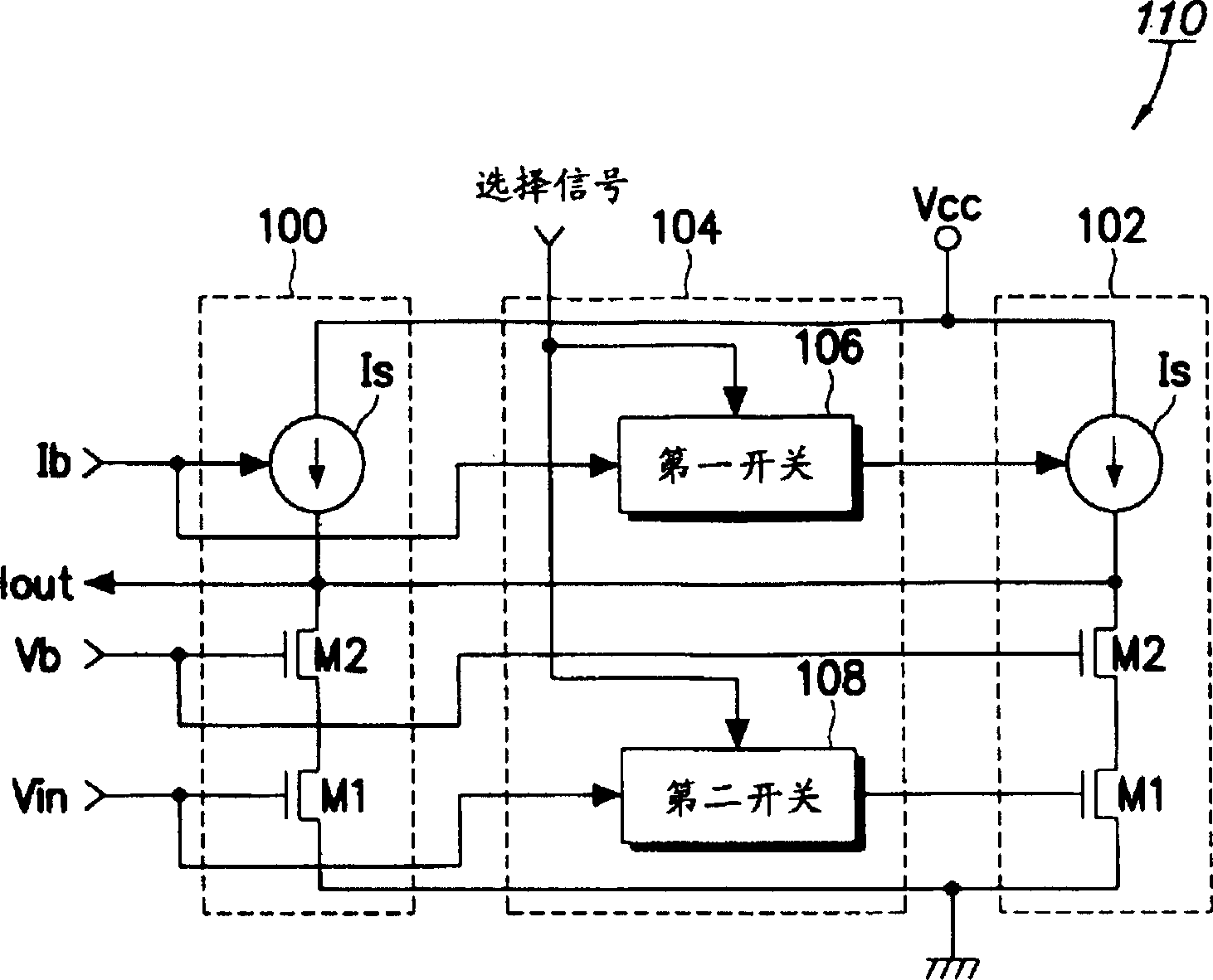
[0020] figure 1 A transconductance variable circuit 110 for variably selecting one of two transconductances is shown. figure 1 The transconductance variable circuit 110 includes first and second transconductance units 100 and 102 and a selection circuit 104 . The two transconductance units 100 and 102 have the same structure and produce the same output transconductance.

[0021] Output terminals of the first and second transconductance units 100 and 102 are generally connected to each other. The input signal voltage Vin, t...


PUM


Abstract

A transconductance variable method and circuit, and a filter and an amplifier using the same. An output transconductance is set by selectively adding at least two transconductances which are identically set according to a select signal for variably selecting the output conductance.

Description

technical field [0001] The present invention relates to transconductors and, in particular, to methods and circuits with variable transconductance, and filters and amplifiers using the methods and circuits. Background technique [0002] Recently, an optical disc reproducing apparatus for reproducing a signal from a disc such as a compact disc (CD), a digital video disc (DVD), etc., shows development toward a high reproduction speed. In an optical disc reproducing apparatus having a low reproduction speed such as normal, double, quadruple or eight speed, since the frequency of picking up an input signal from the disc is low, it is not necessary to use an equalizer. However, frequency characteristics are very important in a high-reproduction-speed optical disc reproduction device. In particular, as the reproduction speed increases, the frequency of the input signal becomes higher. However, since the level of an input signal picked up from a disc becomes lower at high frequen...

Claims


Application Information

Patent Timeline
Patent Type & Authority Patents(China)
IPC IPC(8): H03G3/10G11B20/22H03H11/04
CPCH03H2210/021H03H11/0466H03G5/00H03H2210/012H03F3/72H03H11/0472H03F1/223H03F2203/7236G11B20/22
Inventor 赵启钰金天燮
Owner SAMSUNG ELECTRONICS CO LTD
Learn More