Device having a main support and an equipment support

A kind of equipment support and basic technology, applied in the direction of transmission device, mechanical equipment, lifting device, etc., can solve the problems of expensive size design of mechanism and driving parts, acceleration and force application, etc.

Active Publication Date: 2020-05-01
CONTINENTAL AUTOMOTIVE TECH GMBH
View PDF5 Cites 1 Cited by
  • Summary
  • Abstract
  • Description
  • Claims
  • Application Information

AI Technical Summary

Problems solved by technology

During driving operation of the motor vehicle, large forces can be exerted on the mechanism by various accelerations and force effects that occur next to the motor vehicle, especially if the driver rests his hand or even his entire arm on the operating element while driving , which can lead to expensive dimensioning of the mechanism and the drive, especially when there is a drive

Method used


Image

  • Device having a main support and an equipment support
  • Device having a main support and an equipment support
  • Device having a main support and an equipment support

Examples


Embodiment Construction

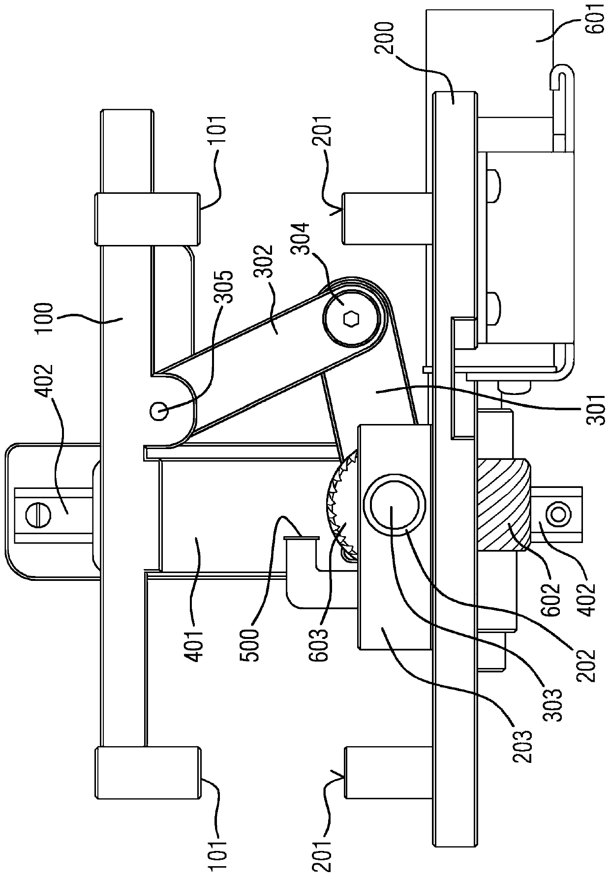
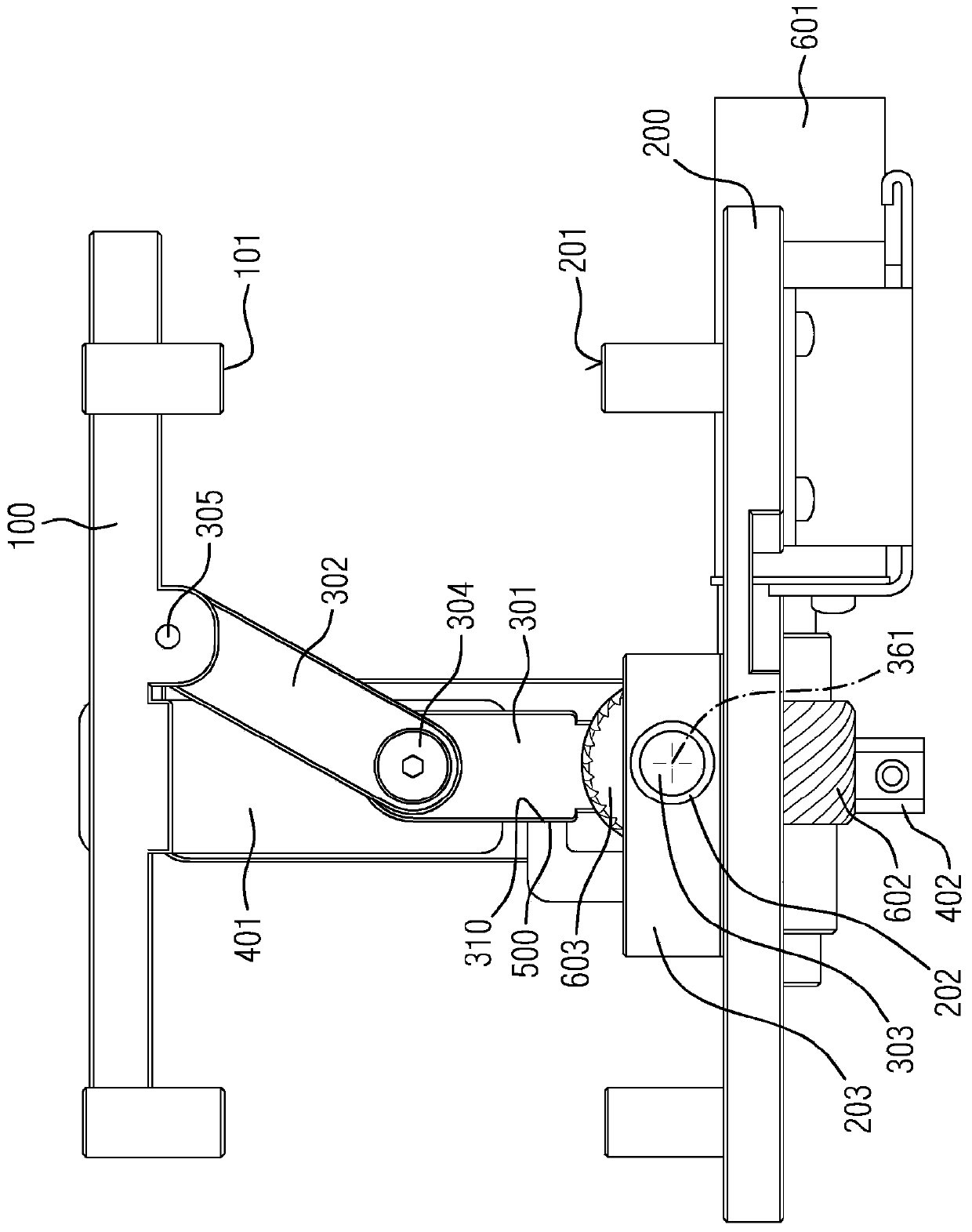
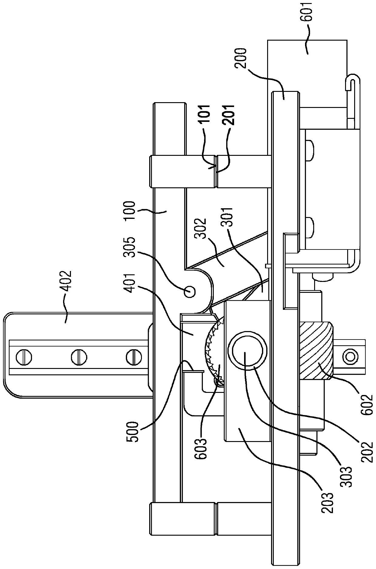
[0031] exist Figure 1-3It can be seen in the equipment support 100, the basic support 200, the first rocker 301, the connecting rod 302, the guide device with the guide slider 401 and the guide rail 402, the stop part 500, the drive in the form of the motor 601, the drive with the worm gear 602 and spur gear 603 for the first transmission. A support frame 101 is formed on the device support 100 , and a first support surface 201 is formed on the base support 200 . in the first position ( image 3 ), the equipment support 100 abuts against the first support surface 201 of the base support 200 through the support frame 101 . However, the support frame 101 and / or the first support surface 201 can also be a separate component, if they are rigidly connected to the equipment support 100 or the base support 200 , respectively. The equipment support 100 and / or the base support 200 can also be designed in such a way that if the support functionality of the equipment support 100 on t...


PUM


Abstract

In the case of a device having a main support (200) and an equipment support (100), the height of which can be adjusted between a first position and a second position relative to the main support (200), and the equipment support (100) in the first position rests on the main support (200) directly or via components connected to the main support, it is provided that the device has a first crank lever (301), wherein the first crank lever (301) is rotatable about a first axis of rotation (361), that a connecting rod (302) is connected to the first crank lever (301) via a first joint (304), and a second joint (305) is connected to the equipment support, that the first crank lever (301) is mounted about a first axis of rotation in a first bearing directly or via a first shaft (303) and the firstbearing (202) is connected to the main support (200), in that the device has a guide (401, 402, 403, 404) for the equipment support (100) in such a manner that the equipment support (100) is guided by means of the guide (401, 402, 403, 404) such that said equipment support is displaceable parallel to the main support (200), that the device has a stop element (310, 721, 722, 723, 724) and a stop (500, 221, 222, 223, 224), that the stop element (310, 721, 722, 723, 724, 725) is connected to the first crank lever (301) or to the connecting rod (302) rigidly or via a second gearing, that the stop(500, 221, 222, 223, 224) is arranged in the main support (200) or is connected to the main support (200), that, by rotation of the first crank lever (301), the equipment support overcomes an upper dead centre when moving from the first to the second position and, upon further rotation of the first crank lever (301), the stop element (310, 721, 722, 723, 724) comes into contact with the stop (500, 221, 222, 223, 224).

Description

technical field [0001] The invention relates to a device with a base support and an equipment support. Background technique [0002] Equipment stands are known from the prior art, the height of which is adjustable relative to the base support between a first position and a second position. The base frame is arranged, for example, in the interior of the motor vehicle and is fixedly connected to the body of the motor vehicle. An operating element, for example in the form of a joystick or a keyboard, or a display element, for example in the form of a display or touch screen, is fastened to the device holder. In order to be able to adapt the position of the device to different users of the motor vehicle or to the operating situation, the height of the base frame and thus the device relative to the body is adjustable from a first position to a second position. (For safety reasons it is often stipulated that the adjustability can only be realized during the stationary state of t...

Claims


Application Information

Patent Timeline
Patent Type & Authority Applications(China)
IPC IPC(8): B60K20/02B60K35/00B60R11/02B60R16/037F16H21/14B60N2/75
CPCB60K20/02B60K35/00B60R11/02F16H21/14B60N2/77B60K37/04B60K37/06B60K2370/67B60K2370/791B60K2370/816B60K2370/744B66F3/12B66F11/00
Inventor W·赞辛格
Owner CONTINENTAL AUTOMOTIVE TECH GMBH
Why Eureka
Try Eureka