Pool floating sludge removal device for sewage treatment

A technology for sewage treatment and floating mud, which is applied in water/sewage treatment, water/sewage treatment equipment, water/sludge/sewage treatment, etc. Complicated problems, to achieve the effect of easy promotion and implementation, simple structure, and high removal quality

Inactive Publication Date: 2020-05-05
陶李
View PDF1 Cites 2 Cited by
  • Summary
  • Abstract
  • Description
  • Claims
  • Application Information

AI Technical Summary

Problems solved by technology

The structure of the device is complicated, the manufacturing cost is high, and the scum is easy to adhere to the inner wall of the treatment tank, causing pollution

Method used


Image

  • Pool floating sludge removal device for sewage treatment
  • Pool floating sludge removal device for sewage treatment
  • Pool floating sludge removal device for sewage treatment

Examples


Embodiment 1

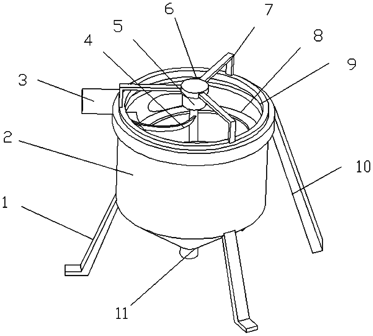
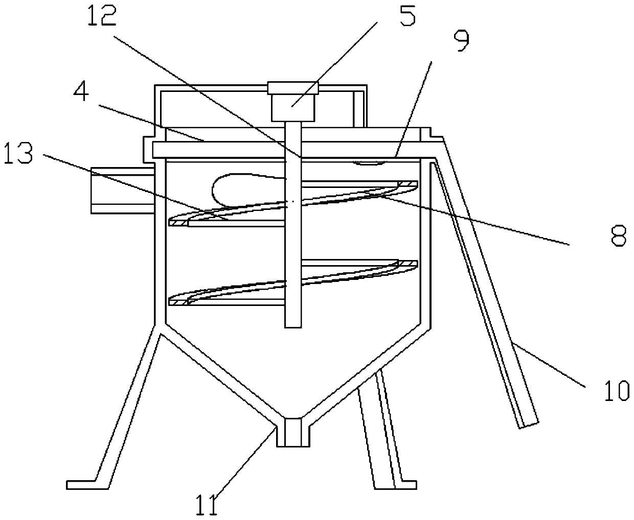
[0026] see Figure 1-3 , a device for removing floating sludge in a sewage treatment pool, comprising a cylinder body 2 and a motor 5 . The bottom of the cylinder body 2 is fixedly provided with several support legs 1, and the support legs 1 have a supporting effect on the cylinder body 2, and the cylinder body 2 can be fixed on the ground through the support legs 1. A water inlet pipe 3 is communicated with the side wall of the cylinder body 2, and sewage enters the interior of the cylinder body 2 from the water inlet pipe 3 for treatment. The top of the cylinder body 2 is fixed to the support frame 7, the middle position of the support frame 7 is fixedly connected with the mounting base 6, the bottom of the mounting base 6 is fixedly mounted with the motor 5, and the output shaft of the motor 5 is coaxially fixedly connected with the rotating shaft 12, and the rotation The shaft 12 is fixedly connected to the inner end of the driving rod 4 and the connecting rod 13, and the...

Embodiment 2

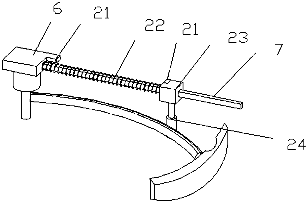
[0030] see Figure 4-5, on the basis of Embodiment 1, the shifting rod 4 includes a rotating plate 16 and a supporting plate 14, the outer ends of the rotating plate 16 and the supporting plate 14 are connected in rotation through a rotating rod 15, and the rotating plate 16 can rotate counterclockwise, so that the floating The slag is dumped inside the collecting tank 9, and the section of the rotating plate 16 is an L-shaped structure, thereby facilitating the collection of scum. The outer end of rotating plate 16 is fixedly connected with protruding rod 17, and protruding rod 17 stretches into the lower edge bottom of material collecting tank 9 and contacts with it, and the lower edge bottom of material collecting tank 9 is provided with protruding 18, when pulling material Rod 4 rotates, and extension rod 17 rotates to the below of protrusion 18, and protrusion 18 extrudes extension rod 17, thereby rotating plate 16 is rotated, and rotating plate 16 is set off, thereby the...


PUM


Abstract

The invention relates to the technical field of sewage treatment, and particularly discloses a pool floating sludge removal device for sewage treatment. The device comprises a barrel and a motor, theside wall of the barrel is communicated with a water inlet pipe; a support frame is fixed at the top of the barrel; the middle position of the support frame is fixedly connected with a mounting seat;a motor is fixedly mounted at the bottom of the mounting seat; an output shaft of the motor is coaxially and fixedly connected with a rotating shaft; the rotating shaft is fixedly connected to the inner ends of the poking rod and the connecting rod, the outer end of the connecting rod is fixedly connected with a spiral scraper, the outer side of the spiral scraper makes contact with the inner sidewall of the barrel, a sludge discharging opening is formed in the bottom of the barrel, a collecting groove is formed in the inner side wall of the barrel, and the outer end of the poking rod is slidably nested in the collecting groove which communicates with a slag discharging groove. The floating sludge on the surface of the sewage is collected to the edge part of the barrel body by the pokingrod, and the sludge attached to the inner side wall of the barrel body is cleaned by the rotation of the spiral scraper. The device has the advantages of simple structure, convenience in cleaning, high removal quality and capability of realizing automatic cleaning.

Description

technical field [0001] The invention relates to the technical field of sewage treatment, in particular to a device for removing floating sludge in a pool for sewage treatment. Background technique [0002] With the development of society, more and more domestic sewage and industrial sewage are affecting the environment. If they cannot be treated in time, they will cause environmental pollution and affect people's lives. There are often floating mud and floating objects on the pool surface of the sewage treatment tank, which has a certain impact on the daily management of the sewage treatment enterprise. The existing sewage treatment tank floating sludge edge removal device (also known as scraper suction machine) includes a central shaft seat, a rotating bridge, a travel motor and a scraper. The central shaft seat is installed in the center of the sewage treatment tank, and the rotating bridge axis is installed On the central shaft seat, scrapers are installed on both sides ...

Claims


Application Information

Patent Timeline
Patent Type & Authority Applications(China)
IPC IPC(8): B01D21/24B01D21/06C02F1/52
CPCB01D21/06B01D21/2438C02F1/5209C02F2201/002
Inventor 陶李
Owner 陶李
Why Eureka
Try Eureka