
Sheet metal part punching die

A sheet metal parts, punching technology, applied in the field of sheet metal parts processing, can solve the time-consuming and labor-intensive problems, and achieve the effect of labor-saving clamping

Inactive Publication Date: 2020-05-05
扬州市祥跃泵业科技有限公司
View PDF0 Cites 1 Cited by
  • Summary
  • Abstract
  • Description
  • Claims
  • Application Information

AI Technical Summary

Problems solved by technology

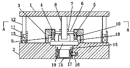
[0003] The purpose of the present invention is to solve the time-consuming and labor-intensive problem of fixing the sheet metal parts on the upper part of the die by means of bolts and other components in the prior art, and propose a punching die for sheet metal parts

Method used


Image

  • Sheet metal part punching die
  • Sheet metal part punching die
  • Sheet metal part punching die

Examples


Embodiment Construction

[0019] The following will clearly and completely describe the technical solutions in the embodiments of the present invention with reference to the accompanying drawings in the embodiments of the present invention. Obviously, the described embodiments are only some, not all, embodiments of the present invention.

[0020] In describing the present invention, it should be understood that the terms "upper", "lower", "front", "rear", "left", "right", "top", "bottom", "inner", " The orientation or positional relationship indicated by "outside", etc. is based on the orientation or positional relationship shown in the drawings, and is only for the convenience of describing the present invention and simplifying the description, rather than indicating or implying that the referred device or element must have a specific orientation, so as to Specific orientation configurations and operations, therefore, are not to be construed as limitations on the invention.

[0021] refer to Figure ...


PUM


Abstract

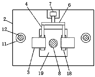
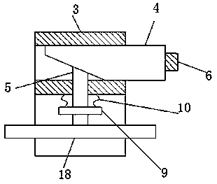
The invention discloses a sheet metal part punching die. The sheet metal part punching die comprises an upper die plate and a lower die plate, wherein a positioning groove is formed in the center of the top of the lower die plate; a through hole is formed in the center of the bottom in the positioning groove; a clamping mechanism is arranged on the top of the lower die plate and comprises two L-shaped fixing blocks symmetrically arranged on the two sides of the positioning groove; square holes are formed in the side walls of the horizontal ends of the fixing blocks; first sliding blocks matched with the square holes are in sliding connection in the square holes; the ends, positioned in the square holes, of the first sliding blocks are arranged to be first slopes, and the other ends of thefirst sliding blocks extend to the outer parts of the square holes; clamping rods vertically arranged are arranged in the square holes; and the ends, away from the positioning groove, of the clampingrods are arranged to be second slopes matched with the first slopes, and the first slopes abut against the second slopes. By means of the sheet metal part punching die, sheet metal parts can be rapidly clamped in a labor-saving manner, and waste generated in the sheet metal part punching process can be conveniently collected.

Description

technical field [0001] The invention relates to the technical field of sheet metal processing, in particular to a sheet metal punching die. Background technique [0002] In the punching process of sheet metal parts, the structure of the punching die is various. When punching a sheet metal part, the sheet metal part needs to be fixed first. At present, people generally use bolts and other parts to fix the sheet metal part. It is fixed on the upper part of the die, which is time-consuming and labor-intensive. Contents of the invention [0003] The purpose of the present invention is to solve the time-consuming and labor-intensive problem of fixing the sheet metal parts on the upper part of the die by bolts and other components in the prior art, and propose a punching die for sheet metal parts. [0004] In order to achieve the above object, the present invention adopts the following technical solutions: [0005] A sheet metal punching die, comprising an upper template and a...

Claims


Application Information

Patent Timeline
Patent Type & Authority Applications(China)
IPC IPC(8): B21D28/24B21D28/34B21D43/00B21D43/20
CPCB21D28/24B21D28/34B21D43/003B21D43/20
Inventor 不公告发明人
Owner 扬州市祥跃泵业科技有限公司
Learn More