Flanging device for tetrafluorohydrazine pipe

A technology of PTFE tube and flanging, which is applied in the field of pipe fitting lining pipe production equipment, can solve the problems of inability to flange the PTFE tube, and achieve the effects of reducing errors, compact device structure and accurate positioning

Inactive Publication Date: 2020-05-05
湖北世纪伟业防腐科技有限公司
View PDF1 Cites 1 Cited by
  • Summary
  • Abstract
  • Description
  • Claims
  • Application Information

AI Technical Summary

Problems solved by technology

[0004] However, due to the different diameters of PTFE tubes, the diameter of PTFE tubes generally ranges from 10cm to 6m, so the above-mentioned device cannot be used to flang any PTFE tubes.

Method used


Image

  • Flanging device for tetrafluorohydrazine pipe
  • Flanging device for tetrafluorohydrazine pipe
  • Flanging device for tetrafluorohydrazine pipe

Examples


Embodiment Construction

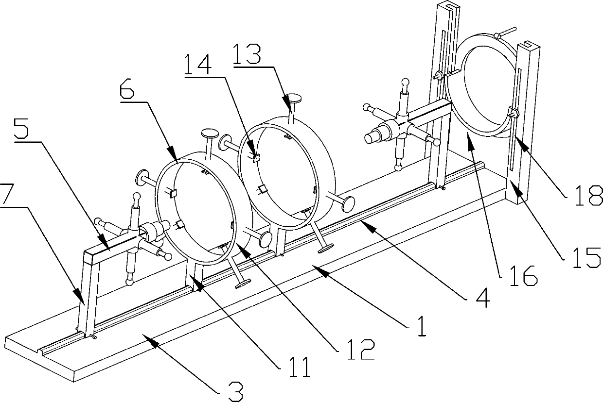
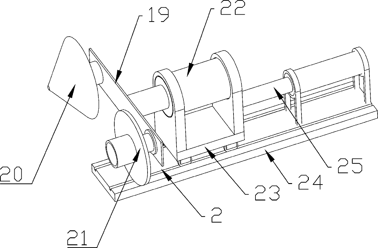
[0025] Such as Figure 1-4 As shown, a PTFE tube flanging device includes a support bracket 1 and a flanging positioning device 2 .

[0026] The support bracket 1 includes a base 3, the base 3 is fixedly connected to the ground through expansion bolts, a slide rail 4 is provided on the base 3, and a centering mechanism 5 is provided on the slide rail 4 radially symmetrically before and after, and the centering mechanism 5 There are two tightening mechanisms 6 between them, and the centering mechanism 5 and the tightening mechanism 6 are used to fix the PTFE tube. The front end of the base 3 is provided with a positioning mechanism, which is used to determine the flanging length of the PTFE tube and support it to facilitate later flanging.

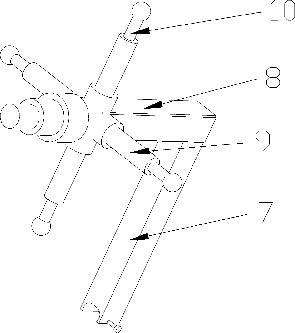
[0027] Specifically, the centering mechanism 5 includes a first leg 7, which is slidably arranged on the slide rail 4, and can pass through the bolt lock in the through hole at the bottom end of the first leg 7 after sliding to a designate...


PUM


Abstract

The invention relates to a flanging device for a tetrafluorohydrazine pipe. The flanging device comprises a supporting bracket and a flanging positioning device. The supporting bracket comprises a base, the base is provided with a slide rail, centering mechanisms are symmetrically and radially arranged on the front and rear portions of the slide rail, one or more jacking mechanisms are arranged between the two centering mechanisms, and the front end of the slide rail is provided with a positioning mechanism. The flanging positioning device comprises a mounting base, the left and right sides ofthe front end of the mounting base are provided with a conical heating flanging mechanism and a stock mold respectively, the rear end of the mounting base is connected with a motor, and the motor isslidingly arranged on a slide base through a support and pushed by an air cylinder to move frontwards and backwards. The flanging device for the tetrafluorohydrazine pipe can improve the work efficiency.

Description

technical field [0001] The invention relates to equipment for manufacturing liner pipes of pipe fittings, in particular to a flanging device for tetrafluoro pipes. Background technique [0002] Steel-lined PTFE pipe is an indispensable and important part in chemical anticorrosion, and it is used in large quantities. The flanging of the sealing surface in the production process is the key process. The method used in the existing technology is to first heat the flanging mold to a certain temperature, and then press the mold on the plastic tube to make it softened by heat and then extend it. Then use the shaping die to compress and compact to cool and shape. The method wastes time, the labor intensity of operators is high, the ambient temperature is high, and the heat source loss is large. According to the change of ambient temperature, secondary processing is often required, and the work efficiency is not high. [0003] The application number is "201721361901.9" patent "a r...

Claims


Application Information

Patent Timeline
Patent Type & Authority Applications(China)
IPC IPC(8): B29C57/12
CPCB29C57/12
Inventor 薛家伟谭银昌王东海
Owner 湖北世纪伟业防腐科技有限公司
Why Eureka
Try Eureka