
Pneumatic tire

A technology of pneumatic tires and tires, which is applied to the reinforcement layer of pneumatic tires, heavy tires, tire parts, etc., and can solve the problems of easy damage and fast wear

Inactive Publication Date: 2020-05-05
TOYO TIRE & RUBBER CO LTD
View PDF19 Cites 0 Cited by
  • Summary
  • Abstract
  • Description
  • Claims
  • Application Information

AI Technical Summary

Problems solved by technology

Since the base rubber layer generally wears quickly and is easily damaged, once the base rubber layer is exposed, the tire must be replaced as soon as possible

Method used


Image

  • Pneumatic tire
  • Pneumatic tire
  • Pneumatic tire

Examples


Embodiment Construction

[0022] Hereinafter, embodiments of the present invention will be described with reference to the drawings.

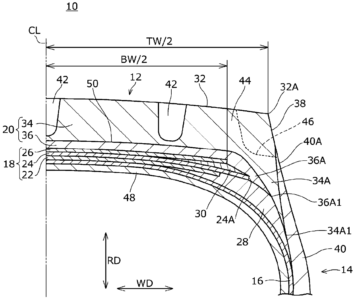
[0023] figure 1 A pneumatic tire 10 according to the illustrated embodiment includes a tread portion 12 constituting a contact surface, a pair of left and right bead portions, and a pair of left and right sidewall portions 14 interposed between the tread portion 12 and the bead portions. The pneumatic tire 10 according to the present embodiment is a heavy-duty pneumatic tire mounted on a truck, a bus, or the like.

[0024] In the drawings, symbol CL denotes a tire equatorial plane corresponding to the tire axial center. In this example, the pneumatic tire 10 is bilaterally symmetrical with respect to the tire equatorial plane CL.

[0025] Here, the tire axial direction refers to a direction parallel to the tire rotation axis, and is indicated by a symbol WD in the drawings. The inner side in the tire axial direction WD refers to a direction approaching the tire equat...


PUM

PropertyMeasurementUnit
hardnessaaaaaaaaaa
hardnessaaaaaaaaaa

Abstract

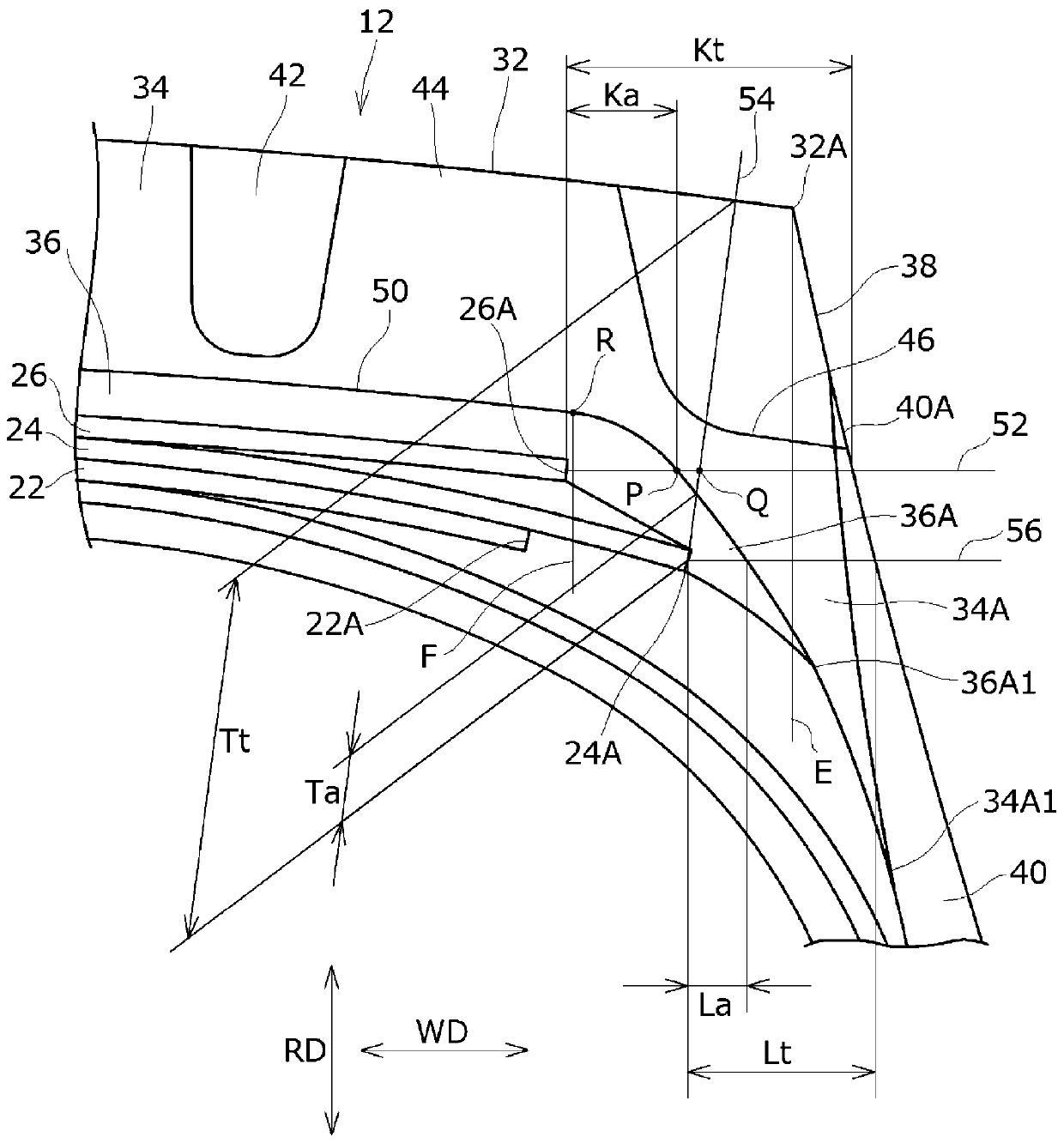
The invention provides a pneumatic tire capable of preventing exposure of the base rubber layer at an early stage while improving the low-fuel consumption property. Tread rubber has a cap rubber layer(34) and a base rubber layer (36). The belt layer includes a widest belt with the maximum width and an outermost belt. An intersection point (P) between an interface between a cap rubber layer and abase rubber layer and an outermost belt lateral reference line (52) extending from an outer end of an outermost belt is positioned on an inner side in a tire axial direction (WD) than an intersectionpoint (Q) between a normal line (54) extending from an outer end of a widest belt to the tread surface and the outermost belt lateral reference line. An outer end of the cap rubber layer is terminatedon an inner side in a tire radial direction than an outer end of the base rubber layer, and the outer end of the base rubber layer is positioned on an outer side in the tire axial direction than an end of the tread surface.

Description

technical field [0001] Embodiments of the present invention relate to a pneumatic tire. Background technique [0002] As is well known, in pneumatic tires mounted on vehicles such as trucks and buses, in order to achieve both wear resistance and low fuel consumption, the crown top rubber layer constituting the tread surface and the rubber layer arranged on the inner side in the radial direction are utilized. The double-layer structure of the base rubber layer constitutes the tread compound. Rubber with excellent wear resistance is used for the crown top rubber layer, and low heat generation rubber with a low loss tangent tanδ is used for the base rubber layer. [0003] For example, Patent Document 1 discloses that the proportion of the base rubber layer with low heat generation is increased in the shoulder portion where heat generation is the largest in the tread portion, and that the thickness of the rubber layer at the top of the crown is greater than that of the shoulder...

Claims


Application Information

Patent Timeline
Patent Type & Authority Applications(China)
IPC IPC(8): B60C11/00B60C9/18B60C11/01
CPCB60C11/00B60C9/18B60C9/185B60C11/01B60C11/005B60C2200/06B60C2009/1871B60C2009/1878B60C2011/0033B60C2013/006B60C2011/0025
Inventor 横枕圣二
Owner TOYO TIRE & RUBBER CO LTD
Learn More