
Cable-stayed bridge with tensioned mid-span main beam

A cable-stayed bridge and main beam technology, applied in the field of bridge structure, can solve the problems of large maintenance and repair workload, poor driving comfort, and high bridge construction cost in the later period, and achieves less maintenance and repair, reduced axial pressure, and low construction cost. Effect

Active Publication Date: 2020-05-05
CHINA RAILWAY ERYUAN ENG GRP CO LTD
View PDF6 Cites 2 Cited by
  • Summary
  • Abstract
  • Description
  • Claims
  • Application Information

AI Technical Summary

Problems solved by technology

[0005] The purpose of the present invention is to: in order to avoid the side span being too long in the prior art, a drawer beam or corbel is set in the middle of the mid-span main girder, which makes the bridge costly, easy to damage, and post-maintenance and repair work To solve the problems of large traffic volume and poor driving comfort, a cable-stayed bridge with a mid-span main girder under tension is provided

Method used


Image

  • Cable-stayed bridge with tensioned mid-span main beam
  • Cable-stayed bridge with tensioned mid-span main beam
  • Cable-stayed bridge with tensioned mid-span main beam

Examples


Embodiment

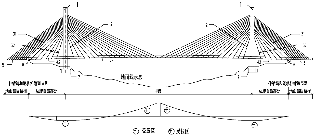
[0027] see Figure 3-Figure 5 .

[0028] The embodiment of the present invention provides a cable-stayed bridge structure system in which the main girder of the mid-span is under tension, which includes a bridge tower 1, a mid-span cable-stayed cable 2, a side-span cable-stayed cable 31 anchored on the ground, a side-span cable-stayed cable anchored to the side-span Side-span stay cables 32 on the main beam, mid-span main beam 41, side-span main beam 42, ground anchorage structures 5 and expansion joints of side-span stay cables. For the cable-stayed bridge built jointly by railways and highways and railways, the track telescopic regulator is also included. The number of bridge towers 1 is at least two, and the overall arrangement of the main girders and stay cables is required to be symmetrical about the longitudinal centerline. The bottom of the bridge tower 1 is the bridge tower foundation 7 .

[0029] The upper end of the mid-span stay cable 2 is anchored on the bridge ...


PUM


Abstract

The invention relates to a bridge structure and particularly relates to a cable-stayed bridge with a tensioned mid-span girder. The bridge comprises at least two bridge towers, mid-span stay cables, stay cables with side spans anchored on the ground, stay cables with side spans anchored on girders, mid-span girders, side-span girders, ground anchoring structures of side-span stay cables and expansion joints, wherein the number of bridge towers is at least two, an upper end of the mid-span stay cable is anchored on the bridge towers, a lower end is anchored on the mid-span girder, upper ends ofthe side-span stay cables are anchored on the bridge towers, lower ends of a part of the side-span stay cables are anchored on the side-span girders, lower ends of the other side-span stay cables areanchored on the ground anchoring structures, the girder is continuous, and the expansion joints are arranged between the ground anchoring structures of the side span girders and the side span stay cables. The cable-stayed bridge is advantaged in that the side span is short, the mid-span girders are tensioned, compared with a bridge in the prior art, the cable-stayed bridge is low in manufacturingcost, high in driving comfort, small in influence on the environment and more suitable for railway cable-stayed bridges and cable-stayed bridges jointly constructed by highways and railways.

Description

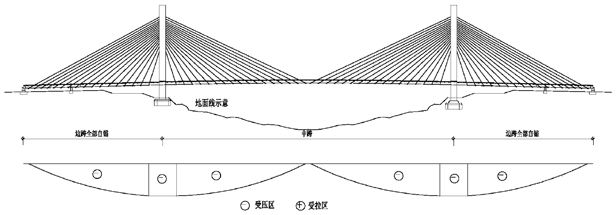
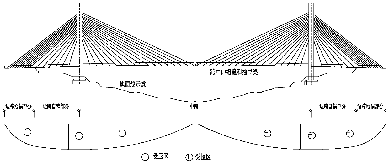
technical field [0001] The invention relates to a bridge structure, in particular to a cable-stayed bridge whose mid-span main girder is under tension. Background technique [0002] In difficult and dangerous mountainous and canyon terrains, due to the constraints of terrain, traffic, and geology, the construction of arch bridges is costly, risky, and has a long construction period. At this time, cable-stayed bridges often become a more suitable structural solution. When the cable-stayed bridge is limited by terrain and geological factors, and cannot set a long enough side span, the conventional cable-stayed bridge form with all main girders self-anchored is adopted, such as figure 1 shown. A cable-stayed bridge whose girders are all self-anchored requires a large amount of foundation excavation to set up side spans, resulting in a lot of engineering waste and great damage to the environment. [0003] In order to solve the shortcoming of long side spans caused by the form ...

Claims


Application Information

Patent Timeline
Patent Type & Authority Applications(China)
IPC IPC(8): E01D11/04E01D21/00
CPCE01D11/04E01D21/00
Inventor 王应良胡玉珠于贞波徐建华王煦丁嘉杰刘伟罗星文陈洪春杨一维
Owner CHINA RAILWAY ERYUAN ENG GRP CO LTD
Learn More