Dismounting device of support for bridge construction

A bridge construction and platform technology, applied in the direction of bridges, bridge construction, erection/assembly of bridges, etc., can solve the problems that the lifting process is difficult to keep stable, the small demolition device cannot provide enough, and the bracket is lifted, so as to avoid unstable clamping, The effect of reducing manual operation and reducing the burden

Inactive Publication Date: 2020-05-05
代国治
View PDF10 Cites 2 Cited by
  • Summary
  • Abstract
  • Description
  • Claims
  • Application Information

AI Technical Summary

Problems solved by technology

[0004] The purpose of the present invention is to solve the disadvantages in the prior art that when the load-bearing capacity of the bridge is weak, the small demolition device cannot provide enough power to lift the bracket, and it is difficult to maintain stability during the lifting process, and proposes a bridge construction. Bracket removal device

Method used


Image

  • Dismounting device of support for bridge construction
  • Dismounting device of support for bridge construction
  • Dismounting device of support for bridge construction

Examples


Embodiment 1

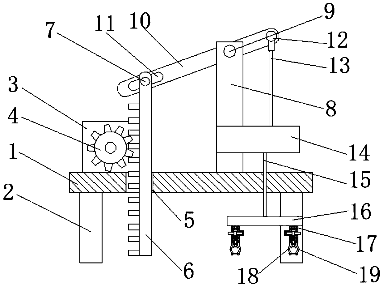
[0029] refer to Figure 1-5 A device for removing a bracket for bridge construction, comprising a platform 1, a plurality of support columns 2 are fixedly installed on the bottom of the platform 1, a motor 3 is fixedly installed on the top of the platform 1, a first through hole 5 is provided on the platform 1, and a first through hole 5 is provided on the platform 1. A tooth plate 6 is slidingly installed in the through hole 5, a gear 4 is fixedly set on the motor 3, and the gear 4 is meshed with the tooth plate 6. The top of the platform 1 is fixedly equipped with a support plate 8, and the top of the support plate 8 is fixedly installed with a Two fixed rods 9, rotating plate 10 is installed on the second fixed rod 9, one end of the rotating plate 10 near the toothed plate 6 is provided with a second through hole 11, and the top of the toothed plate 6 is fixedly equipped with the first fixed rod 7, The first fixed rod 7 is movably installed in the second through hole 11, th...

Embodiment 2

[0040] refer to Figure 1-5 , a device for removing a bracket for bridge construction, comprising a platform 1, the bottom of the platform 1 is fixed with several support columns 2 by screws, the top of the platform 1 is fixed with a motor 3 by screws, and the platform 1 is provided with a first through hole 5. A tooth plate 6 is slidingly installed in the first through hole 5, and a gear 4 is fixedly set on the motor 3, and the gear 4 is meshed with the tooth plate 6. The top of the platform 1 is fixed with a support plate 8 by screws, and the support plate 8 The top of the top is fixed with a second fixed rod 9 by screws, and a rotating plate 10 is installed on the second fixed rod 9. The end of the rotating plate 10 close to the toothed plate 6 is provided with a second through hole 11, and the top of the toothed plate 6 passes through the The screw is fixedly installed with the first fixed rod 7, and the first fixed rod 7 is movably installed in the second through hole 11,...


PUM


Abstract

The invention belongs to the technical field of construction equipment, , particularly relates to a dismounting device for a bridge construction support, in the prior art, and solves problems that when the bearing capacity of a bridge is weak, a small dismounting device cannot provide enough power to hoist a support, stability is difficult to keep in the hoisting process. The device comprises a platform, wherein a motor is fixedly mounted at the top of the platform, a first through hole is formed in the platform, a toothed plate is mounted in the first through hole in a sliding manner, the motor is fixedly sleeved with a gear, a supporting plate is fixedly mounted at the top of the platform, a second fixing rod is fixedly mounted at a top end of the supporting plate, and the second fixingrod is rotatably equipped with a rotating plate. According to the device, the rotating plate is arranged to serve as a lever, power is saved in the lifting process when the support is disassembled, the device can be used for clamping supports of different sizes through clamping plates, a movable rod is used for locking a first clamping jaw and a second clamping jaw, the support is clamped more stably, and the support is prevented from sliding and falling off.

Description

technical field [0001] The invention relates to the technical field of construction equipment, in particular to a device for removing supports used in bridge construction. Background technique [0002] Bridges include lake-crossing bridges, sea-crossing bridges, and viaducts. The lake-crossing bridges and sea-crossing bridges are respectively built on the lake and the sea, while the viaducts are erected on the road. They are all built in relatively high places, thus providing The additional driving routes share the pressure of the road, and because bridges are usually built in relatively high places, building bridges is the same as building buildings, and supports must be set up in advance before they can be built. When the bridge is not built, the site is empty. The bracket is convenient to build, but after the bridge is built, the bracket cannot be easily removed due to the obstruction of the bridge itself, so it is necessary to use the corresponding removal device to remo...

Claims


Application Information

Patent Timeline
IPC IPC(8): E01D21/00
CPCE01D21/00
Inventor 代国治
Owner 代国治
Why Eureka
Try Eureka