Calibration method of camera in CT system

A calibration method and camera technology, applied in the field of medical imaging, can solve the problems of complicated calculation, poor portability, and large size of the customized calibration board, and achieve the effect of reducing the complexity, high convenience, and cost.

Pending Publication Date: 2020-05-05
NANJING ANKE MEDICAL TECH CO LTD
View PDF3 Cites 4 Cited by
  • Summary
  • Abstract
  • Description
  • Claims
  • Application Information

AI Technical Summary

Problems solved by technology

[0009] 1. Higher requirements on the size and flatness of the checkerboard;
[0010] 2. Checkerboard calibration requires a flat checkerboard calibration board. The price of professional calibration boards is high, and the size of customized calibration boards is relatively large. The portability i

Method used


Image

  • Calibration method of camera in CT system
  • Calibration method of camera in CT system
  • Calibration method of camera in CT system

Examples


Example Embodiment

[0034] The present invention will be further described below with reference to the drawings and specific embodiments.

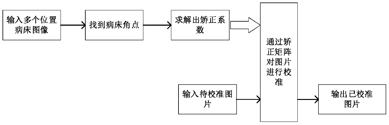
[0035] figure 1 Shown is a flowchart of an embodiment of a method for calibration of a camera in a CT system according to the present invention, such as figure 1 As shown, the method includes the following steps:

[0036] S1: Set up a camera above the CT bed to keep the camera position and angle of view fixed;

[0037] S2: Select one or more corner points of the hospital bed as the reference point, let the hospital bed move in the same direction and equidistantly, and collect the image of the hospital bed through the camera every time it moves. From all the collected images, select the reference point to be away from the camera when collecting The nearest image in the center is used as the standard image;

[0038] S3: Establish the camera perspective coordinate system, and detect the coordinates of the corner points of the hospital bed in the camera perspective coord...


PUM


Abstract

The invention provides a calibration method of a camera in a CT system. The method comprises the following steps: acquiring an image of a CT sickbed in a moving process through the camera with a fixedposition and a fixed visual angle; establishing a camera coordinate system, selecting one or more angular points of a sickbed as reference points, and detecting coordinates of the reference points from all the acquired images through an angular point detection method; selecting an image of which the reference point is closest to the center of the camera during acquisition as a standard image, taking the coordinate of the reference point in the standard image as a standard coordinate, and calculating the standard coordinate of the reference point on other images except the standard image in acamera visual angle coordinate system according to the moving square and the moving distance of the sickbed; finally, solving a correction coefficient matrix capable of mapping the reference point coordinates of each image to the corresponding standard coordinates; and correcting the to-be-corrected image newly acquired by the camera through the correction coefficient matrix. The CT sickbed can bedirectly used for quickly and accurately correcting the camera.

Description

technical field [0001] The invention relates to the technical field of medical imaging, in particular to a camera calibration method in a CT system. Background technique [0002] In the process of applying machine vision, in order to determine the relationship between the three-dimensional geometric position of a point on the surface of a space object and its corresponding point in the image, it is necessary to establish a geometric model of camera imaging, and these geometric model parameters are camera parameters. These parameters must be obtained through experiments and calculations under most conditions. Whether it is in image measurement or machine vision applications, the calibration of camera parameters is a very critical link. The accuracy of the calibration results and the stability of the algorithm directly affect the accuracy of the camera work results. [0003] The checkerboard calibration method is currently the most commonly used camera calibration method. The...

Claims


Application Information

Patent Timeline
IPC IPC(8): G06T7/80
CPCG06T7/80G06T2207/10081G06T2207/20081G06T2207/20164
Inventor 曾凯傅鹏
Owner NANJING ANKE MEDICAL TECH CO LTD
Why Eureka
Try Eureka