Frameless winding tool

A skeleton-free and tooling technology, which is applied to electromechanical devices, manufacturing motor generators, electrical components, etc., can solve the problems of high mold requirements, high skeleton material requirements, poor heat dissipation effect at the stator end, and achieve the effect of preventing scratches.

Inactive Publication Date: 2020-05-05
侯广珍
View PDF0 Cites 0 Cited by
  • Summary
  • Abstract
  • Description
  • Claims
  • Application Information

AI Technical Summary

Problems solved by technology

[0005] In order to solve the above technical problems, the present invention provides a frameless winding tool to solve the problems of poor heat dissipation at the end of the stator winding stator, high requirements for the material of the frame and high requirements for the mold in the existing stator winding

Method used


Image

  • Frameless winding tool
  • Frameless winding tool
  • Frameless winding tool

Examples


Embodiment

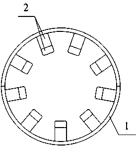
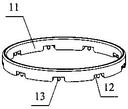
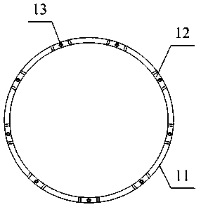
[0024] as attached figure 1 And attached figure 2 As shown, a skeletonless winding tooling includes a tooling ring structure 1 and a tooling plate structure 2, the tooling plate structure 2 is installed in the tooling ring structure 1; the tooling ring structure 1 includes a fixed ring 11. The installation groove 12 and the fixed end 13. The installation groove 12 is set on the lower side inside the fixed ring 11, and the fixed end 13 is integrally arranged in the middle part of the upper end of the inner wall of the installation groove 12.

[0025] as attached Figure 4 As shown, in the above embodiment, specifically, the tooling plate structure 2 includes a fixing plate 21, a connecting piece 22 and a connecting hole 23, and the connecting piece 22 is integrally arranged on the upper and lower parts outside the fixing plate 21 ; The connecting hole 23 is opened on the outside of the connector 22 inside.

[0026] In the above embodiment, specifically, the fixed plate 21 a...


PUM


Abstract

The invention provides a frameless winding tool which comprises a tool ring structure and a tool plate structure. The tool plate structure is arranged in the tool ring structure. The tool ring structure comprises a fixing ring, a mounting groove and a fixing end. The mounting groove is formed in the lower side of the interior of the fixing ring, and the fixing end is integrally arranged in the middle of the upper end of the inner wall of the mounting groove. The frameless winding tool provided by the invention has the beneficial effects that through the arrangement of the tool plate structure, frameworks at the two ends of a stator are replaced during winding, so that the frameworks are prevented from influencing the heat dissipation effect of enameled wires, and the problem that the frameworks made of high materials and high dies are used for winding work is solved.

Description

technical field [0001] The invention belongs to the technical field of electric motors, and in particular relates to a frameless winding tool. Background technique [0002] Concentrated winding motors have fast mechanical winding speed and good consistency. With the development of frequency conversion motors, they have developed rapidly. With the development of technology, it is also found that this winding method also has some shortcomings. For example: both ends of the stator need to use a skeleton; the heat dissipation effect at the end of the stator is poor; the material requirements of the skeleton are high (no soluble matter, refrigerant resistance), and the mold requirements are high (no flashes, burrs and other defects that are easy to fall off), etc. . [0003] The existing stator winding also has the problems of poor heat dissipation effect at the end of the stator, high requirements for the material of the frame and high requirements for the mold. [0004] Ther...

Claims


Application Information

Patent Timeline
Patent Type & Authority Applications(China)
IPC IPC(8): H02K15/085
CPCH02K15/085
Inventor 不公告发明人
Owner 侯广珍
Why Eureka
Try Eureka