Dustproof heat dissipation device for electromechanical equipment

A technology of electromechanical equipment and heat dissipation device, which is applied to the structural parts of electrical equipment, electrical components, transportation and packaging, etc. It can solve the problems of dust coverage and poor heat dissipation effect, achieve uniform heat dissipation, improve heat dissipation efficiency, improve heat dissipation and dust removal effect of effect

Inactive Publication Date: 2020-11-03
赵云赞
View PDF0 Cites 1 Cited by
  • Summary
  • Abstract
  • Description
  • Claims
  • Application Information

AI Technical Summary

Problems solved by technology

[0005] The object of the present invention is to provide a dust-proof and heat-dissipating device for electrom

Method used


Image

  • Dustproof heat dissipation device for electromechanical equipment
  • Dustproof heat dissipation device for electromechanical equipment
  • Dustproof heat dissipation device for electromechanical equipment

Examples


Embodiment 1

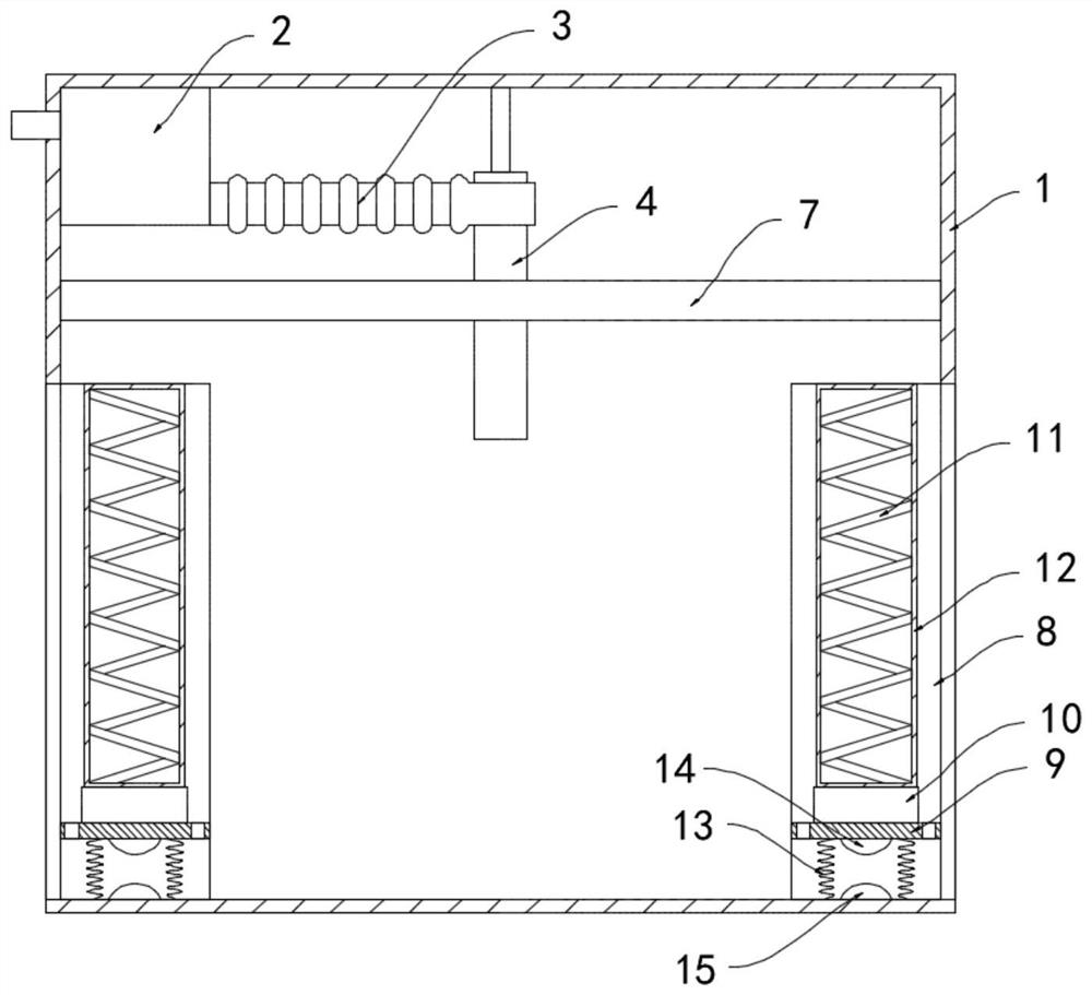
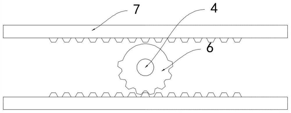
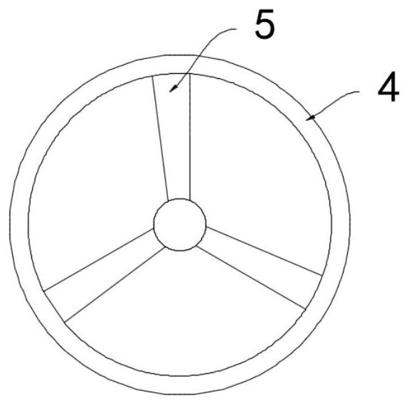
[0022] like Figure 1-3 As shown, a dust-proof and heat-dissipating device for electromechanical equipment includes a casing 1, a suction fan 2 is installed on the inner top surface of the casing 1, and the air outlet of the suction fan 2 is extended to the outside of the casing 1. The suction fan The air inlet of 2 is fixedly connected with a bellows 3, and the other end of the bellows 3 is rotatably connected with a vertically arranged suction pipe 4, and the inner wall of the suction pipe 4 is fixedly connected with a horizontally arranged fan 5, and the suction pipe 4 A half ring gear 6 is fixedly sleeved on the outer coaxial, and racks 7 are fixedly connected to the inner walls of both sides of the housing 1, and the half ring gear 6 meshes with two racks 7 respectively.

[0023] The side wall of the housing 1 is provided with two vertical air intake slots 8, the inner side wall of the air intake slot 8 is slidably connected with a slide plate 9, the upper surface of the ...

Embodiment 2

[0028] like Figure 4 As shown, the difference between this embodiment and Embodiment 1 is that: the bottom of the housing 1 is fixedly connected with a dust collection tank 16, a through hole is provided through the sliding plate 9, and openings are provided on both sides of the dust collection tank 16. The air outlet of the suction fan 2 is fixedly connected with a blowing pipe 17, the lower end of the blowing pipe 17 is extended to the dust collection tank 16, and the outlet end of the blowing pipe 17 is arranged horizontally.

[0029] In this embodiment, the ash shaken off the surface of the dust filter net 12 settles downward, passes through the through hole in the sliding plate 9, and falls into the dust collection tank 16 for collection, which is convenient for removal. When the suction fan 2 works, the blowing pipe 17 The discharged wind is introduced into the dust collection tank 16 and flows quickly in the horizontal direction to blow off the dust in the dust collect...


PUM


Abstract

The invention belongs to the field of electromechanical equipment, and particularly relates to a dustproof heat dissipation device for electromechanical equipment. The dustproof heat dissipation device comprises a shell, wherein a suction fan is mounted on the inner top surface of the shell; an air outlet of the suction fan extends out of the shell, and an air inlet of the suction fan is fixedly communicated with a corrugated pipe; the other end of the corrugated pipe is rotatably connected with a vertically-arranged suction pipe; the inner side wall of the suction pipe is fixedly connected with a horizontally-arranged fan; a semi-gear ring coaxially and fixedly sleeves the suction pipe; the inner side walls of the two sides of the shell are fixedly connected with racks; the semi-gear ringis engaged with the two racks correspondingly, and two vertically-arranged air inlet grooves are formed in the side walls of the shell. According to the present invention, the suction pipe reciprocates left and right in the horizontal direction to suck air in different directions of the electromechanical equipment, so that the uniform heat dissipation of the electromechanical equipment is guaranteed, dust attached to the surface of a dust filter screen can be shaken off, and the situation that the heat dissipation effect of the electromechanical equipment is affected due to blockage of the air inlet groove caused by dust accumulation, is avoided.

Description

technical field [0001] The invention belongs to the field of electromechanical equipment, and in particular relates to a dust-proof and heat dissipation device for electromechanical equipment. Background technique [0002] With the improvement of science and technology and living standards, people's demand for electromechanical equipment in daily life and production is getting higher and higher. From vehicles to various household appliances, computers, printers, etc., electromechanical products have become indispensable in people's lives. , Electromechanical equipment greatly improves people's labor productivity, reduces labor intensity, improves the production environment, and is conducive to human progress and development. [0003] Electromechanical equipment generates a lot of heat during operation, especially in summer when the temperature is high, and the problem of heating of electromechanical equipment is particularly serious. Some existing electromechanical equipment...

Claims


Application Information

Patent Timeline
IPC IPC(8): H05K7/20B08B5/04B01D46/12B01D46/10B01D46/00
CPCH05K7/20145B08B5/04B01D46/10B01D46/12B01D46/0036B01D46/56B01D46/76
Inventor 赵云赞
Owner 赵云赞
Why Eureka
Try Eureka