
Time-based power boost control system

A technology of boost control and time, which is applied in the direction of fluid pressure actuation system safety, fluid pressure actuation system components, fluid pressure actuation device, etc., and can solve problems such as manual activation

Active Publication Date: 2020-05-05
VOLVO CONSTR EQUIP AB
View PDF6 Cites 0 Cited by
  • Summary
  • Abstract
  • Description
  • Claims
  • Application Information

AI Technical Summary

Problems solved by technology

Therefore, in order to boost the pressure relief device, the user must manually activate the boost mode each time it is needed, which can be problematic

Method used


Image

  • Time-based power boost control system
  • Time-based power boost control system
  • Time-based power boost control system

Examples


Embodiment Construction

[0026] Hereinafter, exemplary embodiments of the present disclosure will be described in detail with reference to the accompanying drawings.

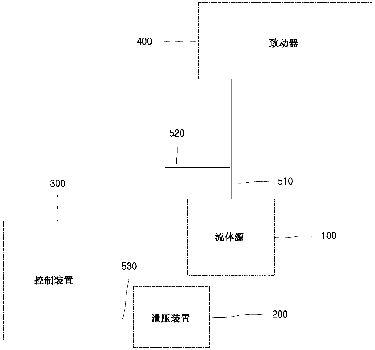
[0027] figure 1 is a block diagram schematically showing the configuration of the power boost control system according to the exemplary embodiment.

[0028] A power boosting control system according to the present disclosure controls boosting of power.

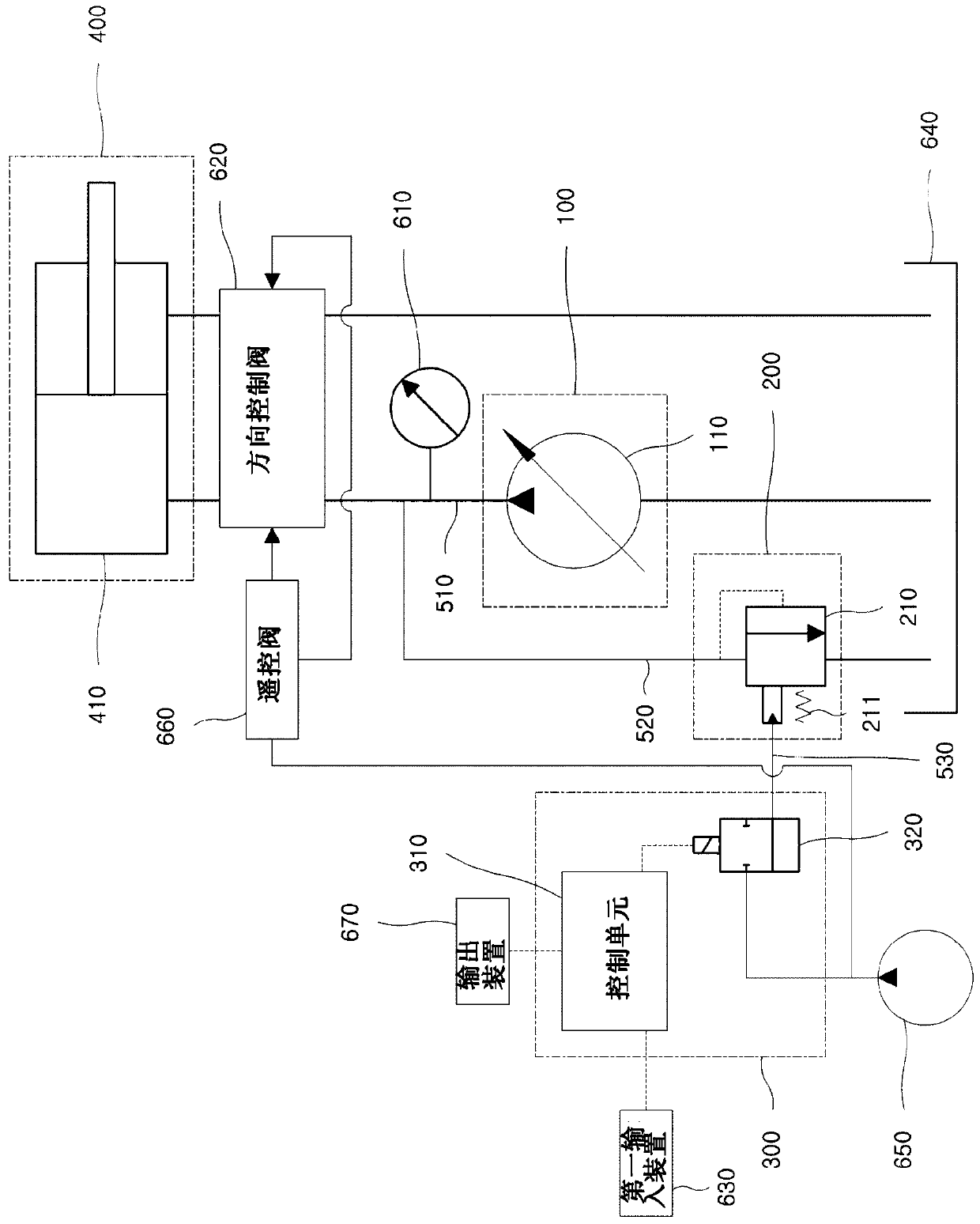
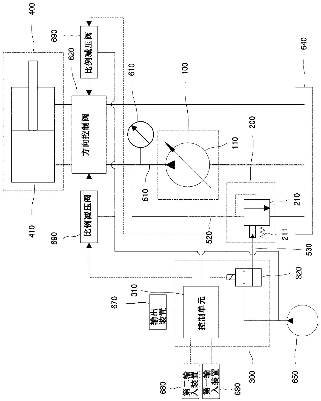
[0029] According to some embodiments, a power boost control system may be used in a fluid actuated machine. According to some embodiments, a power boost control system may be used in hydraulic machines. According to some embodiments, a power boost control system may be used in construction machines, industrial machines, and the like. figure 2 and image 3 An embodiment of a power boost control system for use in a construction machine is shown. However, the present disclosure is not limited thereto, and the power boost control system is applicable to a range of fluid related machin...


PUM


Abstract

The present invention provides a time-based power boost control system. A fluid source supplies fluid. A relief device relieves pressure of the fluid supplied by the fluid source when the pressure ofthe fluid exceeds a relief pressure level. A control device controls the relief device. When a boost mode in which at least a first level of pressure and a second level of pressure, higher than the first level of pressure, are allowed to be selectively used as the relief pressure level is active, a length of a boost-on time in which the second level of pressure is used as the relief pressure levelis shorter than a preset maximum boost-on time limit, and a length of a succeeding boost-off time succeeding the boost-on time in which the first level of pressure is used as the relief pressure level is equal to or longer than a preset minimum boost-off time limit.

Description

technical field [0001] The present disclosure relates to a power boost control system, and more particularly, the present disclosure relates to a time-based boost control system for performing power boost on / off control based on time. Background technique [0002] Various machines that utilize pressurized fluid to generate power are used on construction sites, in various industrial fields, and the like. For example, such machines supply pressurized fluid to actuators, which in turn utilize the pressure of the fluid to work. Since the pressure of the fluid inevitably changes during operation, when the pressure of the fluid rises too high, components to which the fluid pressure is applied may be damaged. Accordingly, there is provided a pressure relief device, such as a pressure relief valve, for preventing respective constitutional devices from being damaged by releasing the pressure of fluid that has increased to a level equal to or greater than a predetermined pressure amo...

Claims


Application Information

Patent Timeline
Patent Type & Authority Applications(China)
IPC IPC(8): F15B11/028F15B13/02
CPCF15B11/028F15B2211/6658F15B2211/6653F15B2211/6309F15B2211/50518F15B2211/5157F15B2211/665F15B2211/76F15B2211/526F15B2211/55F15B20/007F15B13/042F15B21/02F15B21/10
Inventor 李相熙朴海龙
Owner VOLVO CONSTR EQUIP AB
Features
  • Generate Ideas
  • Intellectual Property
  • Life Sciences
  • Materials
  • Tech Scout
  • Unparalleled Data Quality
  • Higher Quality Content
  • 60% Fewer Hallucinations
Learn More