
Electric lifting table

A lifting table and electric technology, applied in the field of lifting table, can solve the problems that cannot be used in combination, the weight of the screw lifting mechanism is heavy, and the transportation and handling are laborious, so as to achieve the effects of reducing the occupied indoor space, light overall weight and wide application range

Pending Publication Date: 2020-05-08
ZHEJIANG LEGE INTELLIGENT DRIVE TECH CO LTD
View PDF0 Cites 5 Cited by
  • Summary
  • Abstract
  • Description
  • Claims
  • Application Information

AI Technical Summary

Problems solved by technology

[0002] Lifting table is a kind of office furniture that can be lifted and adjusted in height. It is suitable for people of different heights, and it is convenient for people to sit and stand alternately. The beam on the top of the column and the table mounted on the beam; the column is equipped with a screw lifting mechanism, and its structure generally includes a screw that is rotatably connected to the inner tube of the column, and the screw is threaded with a base. The base is fixedly connected to the inner wall of the inner tube, the lower end of the inner tube is connected to the base, the upper end of the outer tube of the column is fixedly connected to the shell of the driving mechanism, and the driving mechanism is connected to the lead screw through a transmission device; The structure of the rod lifting mechanism is relatively complicated, and the noise generated by the friction between the screw and the base when it rotates is relatively large. In addition, the weight of the screw lifting mechanism is heavy, and the transportation and handling are laborious; moreover, the use range of the lifting table with this structure Small, cannot be used in combination with walls or screens in the room, and cannot meet people's needs

Method used


Image

  • Electric lifting table
  • Electric lifting table
  • Electric lifting table

Examples

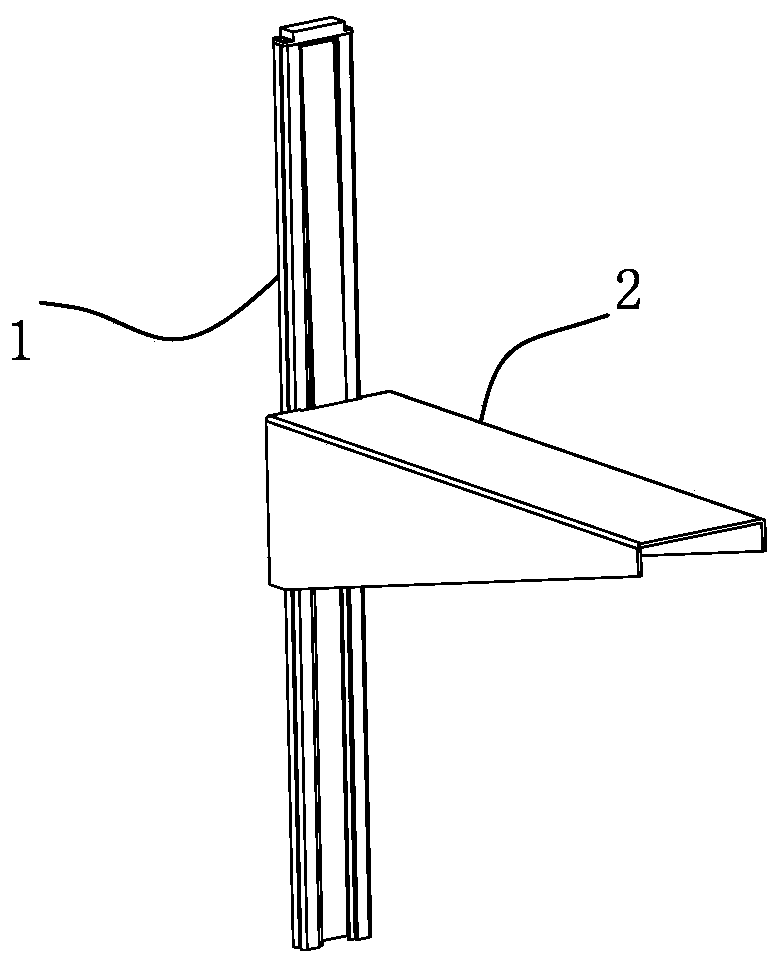
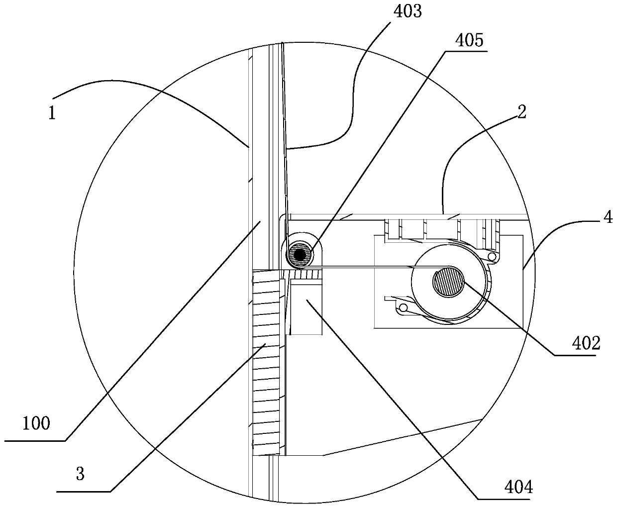
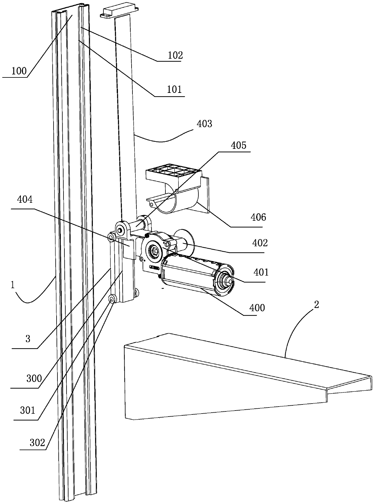

Embodiment Construction

[0023] The present invention will be described in further detail below in conjunction with the accompanying drawings and specific embodiments.

[0024] Such as figure 1 , figure 2 , image 3 with Figure 4 shown;

[0025] The present invention is an electric lifting table, which includes at least one column 1 installed on the wall or screen; the sliding part 3 which is arranged on the column 1 and can slide up and down relative to the column 1 is connected with the sliding part 3 and connected with the sliding The support frame 2 that slides synchronously with the parts 3, the support frame 2 is used for installing the table board; the drive device 4, the drive device 4 includes a drive motor 400, a transmission assembly 401, a winding mechanism 402 and a winding part 403; The drive motor 400 described above is connected to the winding mechanism 402 through the transmission assembly 401, one end of the winding member 403 is connected to the winding mechanism 402, and the ...


PUM


Abstract

The invention discloses an electric lifting table. The electric lifting table comprises at least one stand column installed on a wall or a screen, a sliding piece arranged on the stand column and capable of sliding up and down relative to the stand column, a supporting frame connected with the sliding piece and sliding synchronously with the sliding piece and used for allowing the table board to be installed, and a driving device comprising a driving motor, a transmission assembly, a winding mechanism and a winding piece. The driving motor is in transmission connection with the winding mechanism through the transmission assembly, one end of the winding piece is connected with the winding mechanism, and the other end of the winding piece is connected with the stand column. When the windingmechanism rotates, the winding piece is wound on the winding mechanism or released from the winding mechanism and used for adjusting the lifting height of the supporting frame. The electric lifting table is simple in structure, low in noise during lifting, light in weight and convenient to carry, and can be combined with a wall or a screen in a room for use.

Description

technical field [0001] The invention relates to the technical field of lift tables, in particular to an electric lift table. Background technique [0002] Lifting table is a kind of office furniture that can be lifted and adjusted in height. It is suitable for people of different heights, and it is convenient for people to sit and stand alternately. The beam on the top of the column and the table mounted on the beam; the column is equipped with a screw lifting mechanism, and its structure generally includes a screw that is rotatably connected to the inner tube of the column, and the screw is threaded with a base. The base is fixedly connected to the inner wall of the inner tube, the lower end of the inner tube is connected to the base, the upper end of the outer tube of the column is fixedly connected to the shell of the driving mechanism, and the driving mechanism is connected to the lead screw through a transmission device; The structure of the rod lifting mechanism is re...

Claims


Application Information

Patent Timeline
IPC IPC(8): A47B9/12A47B5/00A47B13/02A47B13/00
CPCA47B5/00A47B9/12A47B13/003A47B13/02
Inventor 项乐宏蒋领辉陈旭峰
Owner ZHEJIANG LEGE INTELLIGENT DRIVE TECH CO LTD
Learn More