
Transnasal feeding tube

A nasal and catheter technology, applied in the field of medical devices, can solve problems affecting the health of patients

Pending Publication Date: 2020-05-08
宁波天益医疗器械股份有限公司
View PDF2 Cites 0 Cited by
  • Summary
  • Abstract
  • Description
  • Claims
  • Application Information

AI Technical Summary

Problems solved by technology

Existing nasal feeding tube is to offer several infusion holes at the proximal end of its catheter, such as Figure 13 Shown; Chinese patent document CN205994749U and U.S. patent document US20030163100A1 all belong to this existing nasal feeding tube; this existing nasal feeding tube will accumulate a section of liquid nutrients at the terminal until the end of a use cycle, and there is The risk of affecting the patient's health due to the deterioration of the liquid nutrients accumulated at the terminal during the period

Method used


Image

  • Transnasal feeding tube
  • Transnasal feeding tube
  • Transnasal feeding tube

Examples


Embodiment 1

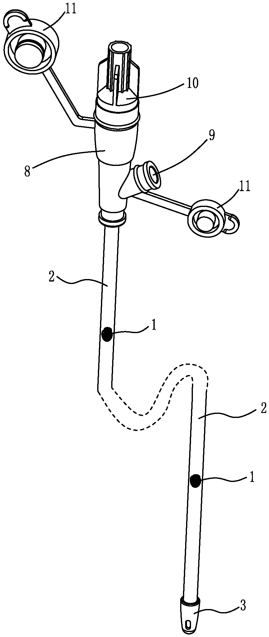
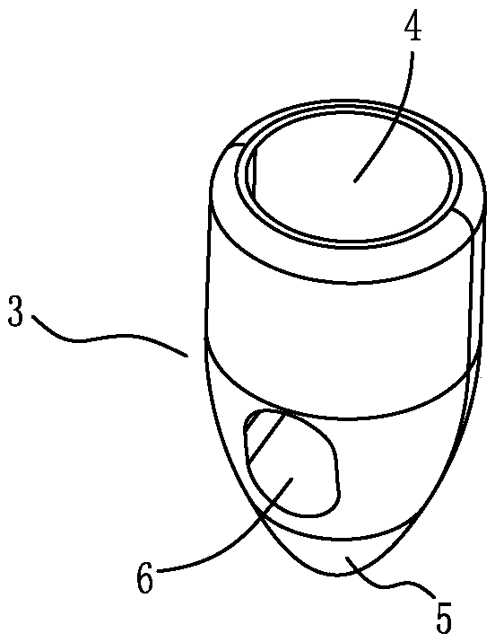
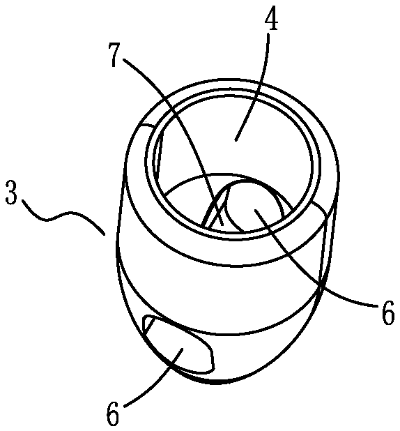
[0032] Embodiment 1: as figure 2 , image 3 , Figure 4 As shown, the shape of the terminal 3 is bullet-shaped and has a circular arc tip; the bottom 5 of the terminal 3 is a spherical crown entity from the circular arc tip to the bottom wall of the infusion hole 6, which is easy to guide when inserted, and It can ensure that it will not be punctured by the first end of the guide wire during normal operation. The end 3 is provided with a through hole running through both sides of the opening 4, and a hemispherical groove 7 is formed at the bottom 5, such as Figure 6 Shown; Form 2 infusion holes 6 of symmetry in opening mouth 4 both sides like this, the hole bottom wall of infusion hole 6 is exactly the groove bottom wall of hemispherical groove 7, makes liquid nutrient nowhere accumulate. The inner wall of the mouth 4 of the end 3 is in an arc transition with the hemispherical groove 7, which facilitates the flow of liquid nutrients.

Embodiment 2

[0033] Embodiment 2: Two more symmetrical infusion holes 6 are added above the two infusion holes 6 on the terminal 3, such as Figure 5 Shown; Make the liquid nutrition flow out more smoothly. Others are the same as in Example 1.

Embodiment 3

[0034] Embodiment 3: The end 3 is provided with two through holes crossing each other through the two sides of the opening cavity 4, and the hemispherical grooves 7 intersecting each other are formed at the bottom end 5, as Figure 7 Shown; In this way, four infusion holes 6 uniformly distributed along the circumference are formed around the opening 4 . Others are the same as in Example 1.


PUM


Abstract

The invention provides a transnasal feeding tube that the end of a catheter cannot accumulate fluid nutrients. The feeding tube includes a catheter (2); a guiding wire (1) is arranged in the catheter(2); the end of the catheter (2) is fixedly connected to an end head (3); the end head (3) is provided with an open cavity (4); the end of the catheter (2) is inserted into the open cavity (4) of theend head (3); a bottom end (5) below the cavity bottom of the open cavity (4) is a solid body; the side surface of the open cavity (4) of the end head (3) is provided with at least one infusion hole (6); and the bottom walls of the infusion holes (6) are not higher than the lowest part of the cavity bottom of the open cavity (4). Thus, the problems of the influences on patient health due to the accumulation on the ends of existing transnasal feeding tubes can be solved.

Description

technical field [0001] The invention belongs to the technical field of medical devices and relates to a nasal feeding tube. Background technique [0002] Some patients are unable to eat on their own due to illness or injury. A nasal feeding tube is a device that provides liquid nutrition to these patients. It mainly includes a catheter made of polymer materials, and a metal guide wire is arranged in the catheter. When in use, the metal guide wire guides the bones and muscles, and the catheter enters the gastric cavity or intestine from the patient's nasal cavity. This process can also be performed on the monitoring instrument. It is carried out under monitoring; after that, the metal guide wire is pulled out, and liquid nutrients are injected into the catheter, and the liquid nutrients flow into the gastric cavity or intestine of the patient through the infusion hole at the end of the catheter. Usually, the nasal feeding tube is not reused and is a one-time consumable. Eac...

Claims


Application Information

Patent Timeline
IPC IPC(8): A61J15/00
CPCA61J15/0007A61J15/0026
Inventor 刘亚龙张若愚施科磊张文宇吴斌吴志敏
Owner 宁波天益医疗器械股份有限公司
Learn More